Hive Multizone S Plan Wiring

Joined
3 Dec 2018
Messages
7
Reaction score
0
Country
United Kingdom
Hello everyone,

First post so please be kind. I've recently moved into a new build with a dual zone setup as below (I believe it is S Plan):

Worcester Greenstar 14i
Honeywell ST9100 programmer by the boiler
2x Honeywell CM907 - one in each zone.

I going to fit a Hive multizone setup with 2 receivers; one dual zone and one single zone. - I fitted a single zone CH and HW Hive setup in my last house without any problems, but the wiring was a lot simpler than the current setup.

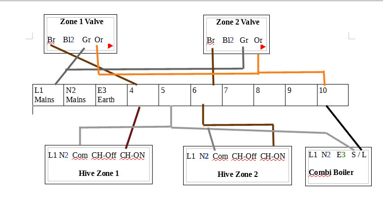
Below is what the setup currently looks like, I have omitted the L & N wires as well as the HW wiring because I am okay with those:

**Edit - everything other than the room thermostats are located in the garage so running any new wires needed would be simple

33uzsb9.png


The Hive wiring diagrams are here:

2ebe1av.jpg


Initially I was going to join 3 in the single channel receiver (CH On) to 4 in the wiring centre and bridge COM and L, then join 4 in the dual channel receiver (CH on) to 4 in the wiring centre and disconnect both existing room thermostats.

But surely that would leave both heating valves without a SL feed? If I were to join the L and SL behind each room thermostat would that be a solution?

Any input would be appreciated!
 
Sponsored Links
Has the search button broke again?

I did actually search for 'hive multizone' as my first port of call and read through all 2 page of results, they were mostly talking about . If you can point me in the direction of more helpful advice then I’ll gladly remove this thread.

Alternatively, you could offer me some of your wisdom? Based on your post count you are clearly a lot more knowledgeable than I am on this matter...it really would be appreciated (y)
 
As Dan said the info is all out there, you just have to adapt it for your personal installation. However, I can give you some pointers:

First of all, there is something wrong with your diagram. The thermostat SL wire will be connected to the appropriate motorised valves brown wire, not their internal micro switches (grey wire) as you show.

That aside, as you will only be controlling the central heating with the Hive's (ie no hot water control) then the simplest way is to remove the existing wire between the programmer (4) and the wiring centre terminal strip (4). Then link the wiring centre terminal strip (4) to (Mains L). That will now put a permanent live on the red wire in the cables that go to the thermostat (L) terminals.

With a permanent live now connected, this allows the existing thermostat cable to be re-routed to the new Hive receivers (or you can remove them and run new cables in their place, whichever is easier). As your system doesn't include hot water control, you should use 2 x Single Channel Versions of the Hive receiver.

Once the existing thermostat cables are re-routed to their appropriate Hive receivers, then:

The red wire (which is now a permanent live) would connect to the Hive Single Channel receiver (L) and also be linked to Com (1)
The black wire marked SL would then connect to the Hive (3) Heating on
Then you will need to run a neutral from the wiring centre to the Hive (N)

This is repeated for the other room thermostat.

As the existing programmer now has no function you can physically remove it, and the wiring connected to it if you like.
 
Sponsored Links
As Dan said the info is all out there, you just have to adapt it for your personal installation. However, I can give you some pointers:

First of all, there is something wrong with your diagram. The thermostat SL wire will be connected to the appropriate motorised valves brown wire, not their internal micro switches (grey wire) as you show.

That aside, as you will only be controlling the central heating with the Hive's (ie no hot water control) then the simplest way is to remove the existing wire between the programmer (4) and the wiring centre terminal strip (4). Then link the wiring centre terminal strip (4) to (Mains L). That will now put a permanent live on the red wire in the cables that go to the thermostat (L) terminals.

With a permanent live now connected, this allows the existing thermostat cable to be re-routed to the new Hive receivers (or you can remove them and run new cables in their place, whichever is easier). As your system doesn't include hot water control, you should use 2 x Single Channel Versions of the Hive receiver.

Once the existing thermostat cables are re-routed to their appropriate Hive receivers, then:

The red wire (which is now a permanent live) would connect to the Hive Single Channel receiver (L) and also be linked to Com (1)
The black wire marked SL would then connect to the Hive (3) Heating on
Then you will need to run a neutral from the wiring centre to the Hive (N)

This is repeated for the other room thermostat.

As the existing programmer now has no function you can physically remove it, and the wiring connected to it if you like.

Many thanks for the helpful reply. The system is going to be used to control the HW, I just didn't include it in the diagram to try and simplify it. The call for HW comes from the programmer (1) and goes to the wiring centre (6) before running to the thermostat on the cylinder.

This will be replaced with a wire running from the Hive dual receiver (3) to the wiring centre (6).

I am sure that you are right about the wiring for the valves...it was late last night when I drew the diagram, I will confirm when I get in from work though.

I was planning on removing the existing thermostat wiring, so if I run a permanent live to terminal 4 in the wiring centre and then connect everything else as shown (obviously HW as well), would that work?

Hive-revised.png
 
I know how hot water is wired to a Hive. Only you failed to mention that crucial piece of information in your original post that changes much of the set up. I cannot figure how you thought omitting a third of the system you want to control with the Hive, wasn't important. Anyway:

The Hives will need a permanent live and neutral connecting so you can connect the live via (4) if it's linked to the Mains L (1) as you suggest.

And as you show / say:
  • The dual channel hive 4 will go to the appropriate motorised valves brown wire
  • The dual channel hive 3 will go to the cylinder thermostat
  • The single channel Hive will go to the appropriate motorised valves brown wire
  • The single channel Hive 1 is also linked to Com 1
  • Existing programmer to be removed

Again, thank you for the reply. I did mention that I had omitted the HW wiring because I was happy with how to wire it to the cylinder thermostat - my fault though, I should have made it clearer - apologies for any confusion.

Will it matter that the boiler is connected to (4) if I link it to (1)?

I will give it a go this evening
 
Sorry, I've no idea! You don't show what it's connected to at the boiler end, and like the motorised valve wiring I'm not convinced it's correct anyway.

With an S-Plan, the thermostat will be wired to the motorised valves brown wire, so that when the thermostat switches 'on' it it powers the valve motor to wind the valve open. The thermostats are not connected to the boiler, as your drawing seems to show. The grey and orange wires from the motorised valves are what control the boiler, they are responsible for switching it on when the valve has wound fully open.

However, if you are worried about terminal 4 being made live, it already is (according to your diagram, if it's right of course) when the programmer switches the heating on. However if you are worried you can skip the link to 4 and wire the Hive L terminals directly to '1 Mains L' instead.

There's a useful animated diagram here, that explains how the S-Plan works. If you click on the S-Plan links you will see what happens and when.

Thank you - that animation is excellent, I now understand. I'll trace all of the wires back from the wiring centre this evening to check, but I am pretty sure that it is the same as the animation. :)
 
Okay, so I wired it up as suggested, initially without connecting 4 to PL.

Hot water worked fine, reciever lit up, valve opened, boiler fired.

I then tested the CH, both valves operate correctly, the receivers both light up and the boiler shows the radiator symbol but doesn’t actually fire.

I then tried it with a PL to 4, this time the boiler wouldn’t fire at all when any of the requests for heat were made.

There is a four core & earth running from the boiler into the wiring centre.

Live & Neutral are connected as expected.
Grey goes to 10
Black goes to 4

I have removed the bridge from PL - 4, so there is now nothing connected to 4 other than the black from the boiler.

The other wiring in the centre:

From the cylinder stat:

Brown - 6
Blue - 8
Grey/Black unused

Cylinder valve:

Brown - 8
Red - 10
Blue - N
Grey - L

Any further advice would be amazing, I can provide photos if that would help?
 
In fact, after a bit more playing, they do all cause the boiler to fire, but only if there is a minute or so between turning one off and another one on.

E.g

Turn HW on, everything works. Turn HW off and then immediately switch downstairs CH on, boiler doesn’t fire.

However, if I wait approximately 2 minutes between switching HW off and CH on it works.

Is this normal?
 
It may well be Normal. These days boilers have all sorts of features, and settings that can be adjusted when they are commissioned. This question would have to be answered by a Gas Safe guy familiar with commissioning your boiler.

Boilers also generally generate considerably more heat than the radiators can use, so there can be delay if they start up whilst already hot as they disperse their hot contents before firing up again.

I wouldn't worry about it too much though, it's probably always been like that and you just haven't noticed. As far as the new wiring is concerned. All the Hive provides is an on/off switch exactly the same as your old programmer. It's the motorised valves via their internal switches that control the boiler and that hasn't been altered, which if the boiler is indicating heat is being requested (radiator symbol) that's because the motorised valves working just fine.

I then tried it with a PL to 4, this time the boiler wouldn’t fire at all when any of the requests for heat were made.
Sounds like you were mixing and matching (or probably mis-matching) options so it wouldn't work
 
Last edited:
View media item 102376View media item 102363Hi Guys,
I already have a HIVE single channel system installed with the combi boiler. I have now created two separate zones with two s-valves. got my hive multizone delivered yesterday but cannot get my head around the wiring. I will appreciate if one of you can do the diagram for me. I did try to search the other wiring diagram I manage to find are with the hot water and thermostats which is very confusing.

1. Installed single channel Hive is connected to SL from the boiler to "1-com" and "3-CH on" .
2. Live from mains connected to L of Hive and Boiler, and same with N
3. Two S-Valves not wired
4. Hive Multizone new receiver not wired

I will appreciate any help to conform to my wiring plan. I do not want to mess it up by using my half knowledge.

Questions :

- Two cables coming from Boiler S/L
- Com from Hive
- Why Com and not CH-Off


Regards
 

Attachments

  • dia2.jpg
    dia2.jpg
    53.1 KB · Views: 2,537
Last edited:
The only connection to the boiler switched live should come from the two motorised valves orange wires. Not the thermostats. The thermostats should not be connected to the boiler. This is because, the thermostats operate the motorised valves and when the valves are open, the motorised valves start the boiler.

The Hive 'Common' should be connected to a permanent live supply. Usually it is simply linked to the Hive L terminal
The Hive 'Heating on' will then operate the motorised valve associated with it

The Hive 'Heating off' terminal becomes live when the heating goes off, and there are very few systems with extremely rare MOMO valves that use it. They are almost as rare as hen's teeth.
 
Thanks for your reply, I have been waiting for it desperately.


5 Core cable coming from the boiler.

L , N, E and a Black and a Grey from stats, which are connected to Hive Comm and CHON currently in the stand-alone system.


As per your advice, Black will go to 10 and bridge with both the Oranges from the Valves as shown in my diagram.

What will happen to the Grey from the boiler ?
 

Attachments

  • dia3.jpg
    dia3.jpg
    53 KB · Views: 417

DIYnot Local

Staff member

If you need to find a tradesperson to get your job done, please try our local search below, or if you are doing it yourself you can find suppliers local to you.

Select the supplier or trade you require, enter your location to begin your search.


Are you a trade or supplier? You can create your listing free at DIYnot Local

 
Sponsored Links
Back
Top