Taking forever to pressurise central heating system. Why is this so?

You seem to be describing a sealed heating system with gravity (tank-fed) hot water.

Could you post pics of your airing cupboard showing your cylinder, filling loop and expansion vessel?
Bump.
 
Sponsored Links
Is the silver coloured braided flexible hose in your pic severely bent downward,close to where it meets the red expansion vessel ??
It appears so ,even though you stated earlier that it isn't .
 
Last edited:
Could you post pics of your airing cupboard showing your cylinder, filling loop and expansion vessel?
You read my mind BlueLoo! I have just returned from doing so. Please find attached.

What I cannot understand is this: From what I've read on line, the expansion vessel (EV) is normally attached to the hot water feed, usually in line with the heating coil in the hot water storage tank. This is to cushion any excessive water expansion caused by heating. And any even more excessive expansion is vented by the pressure relief valve. I've drawn a rough schematic and attached to this post.

Is this right? Because, if it is right, then I cannot understand what the plumber who installed our expansion vessel has done, as it appears to be fed COLD water from the loft tank (the flexible grey tubing attached to the braided tube connector, the other end of which goes to the EV), then the 22mm copper pipe goes from the EV to the cold water feed into both the boiler and the bathroom (IMG_8345 to IMG_8347). So how can the EV dissipate any HOT water expansion?
 

Attachments

  • IMG_8343.JPG
    IMG_8343.JPG
    319.5 KB · Views: 40
  • IMG_8344.JPG
    IMG_8344.JPG
    307.5 KB · Views: 40
  • IMG_8345.JPG
    IMG_8345.JPG
    281.1 KB · Views: 41
  • IMG_8346.JPG
    IMG_8346.JPG
    264.2 KB · Views: 39
  • IMG_8347.JPG
    IMG_8347.JPG
    252.3 KB · Views: 43
  • GRAVITY FED SCHEMATIC.gif
    GRAVITY FED SCHEMATIC.gif
    234.3 KB · Views: 44
terryplumb said:


Is the silver coloured braided flexible hose in your pic severely bent downward,close to where it meets the red expansion vessel ??
It appears so ,even though you stated earlier that it isn't .


I've attached a side view photo of the connection of this braided tubing to the EV to this post. There's no kinking as you can see.
 

Attachments

  • IMG_8348.JPG
    IMG_8348.JPG
    212.2 KB · Views: 29
Sponsored Links
Is this right? Because, if it is right, then I cannot understand what the plumber who installed our expansion vessel has done, as it appears to be fed COLD water from the loft tank (the flexible grey tubing attached to the braided tube connector,

Has he fed actually fed it from the loft tank, or maybe he fed it from the cold water feed to the tank?
 
Harry asked:
Has he fed actually fed it from the loft tank, or maybe he fed it from the cold water feed to the tank?

I'm not sure. I'll go up to the loft & check.
 
You have a complete misunderstanding of your plumbing set up.
At the moment your system pressure doesn't need topping up , so I assume it's for future reference about why it takes a long time ?
 
Here we go:
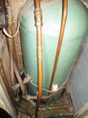
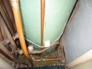
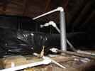
IMG_8349 is a photo of the front of the plastic loft water tank (coffin), showing three of the four connections to it. The Uppermost inverted L shaped PVC pipe lagged on its vertical section, is the cold water mains feed. This enters the tank through its left square top hatch. The ball valve is attached to the end of this pipe. The next pvc pipe down, is the tank overflow pipe. Of the two lowermost pipes, the left one goes to what was the garage and is now in the (slow) process of being converted into a workshop. The one on the right is the one which goes down into the Airing Cupboard to feed the EV.

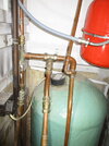
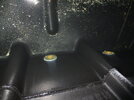
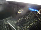
IMG_8354 is a shot of the inside front of the coffin tank, through the water. The upper part of the photo is the base of the tank. The lower part of the photo is the inside of the front wall of the tank. The outlet on the left goes to the garage, the one on the right goes to the Airing Cupboard.

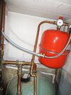
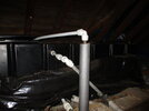
IMG_8355 is a shot of the inside back wall of the tank. The single outlet seen, feeds cold water to the bathroom & WC.

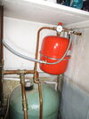
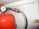
IMG_8361 is there to show as much as I could capture in a photo of the outside of the coffin tank.

So, yes, the airing cupboard IS fed from the loft tank and not from the mains.
 

Attachments

  • IMG_8354.JPG
    IMG_8354.JPG
    379.3 KB · Views: 38
  • IMG_8355.JPG
    IMG_8355.JPG
    348.4 KB · Views: 30
  • IMG_8349.JPG
    IMG_8349.JPG
    311.1 KB · Views: 32
  • IMG_8361.JPG
    IMG_8361.JPG
    209.8 KB · Views: 35
terryplumb said:

You have a complete misunderstanding of your plumbing set up.
At the moment your system pressure doesn't need topping up , so I assume it's for future reference about why it takes a long time ?


Pardon me Terry, but my question was NEVER about topping up. I KNOW that I'm at the correct pressure. My question was why it takes so long to pressurise (see post #1 for details).

EDIT: And what am I misunderstanding about my setup? Is any part of my layout description in post #18 incorrect?
 
Yeah ,got that. But you don't understand your system ,and are posting incorrect information. With regard to the slow filling / topping up pressure,that can be a number of things. First thing to establish is the isolation valve and flexi hose are delivering mains pressure and good flow to the NR valve. If they are ,suspect the NR valve is the issue.
Trace the source of the plastic pipe that connects to the isolation valve.
 
Which NR valve are you talking about Terry? Please mark it if it appears in one of the photos which I've uploaded.
EDIT: Trace the source of the plastic pipe that connects to the isolation valve.
I have. Read the 1st paragraph on past #23, the source is the Loft tank.
The Isolation valves (there are 3 of them) are in the braided flexihose.
EDIT 2: Terry you are probably right about the source of the plastic hose. But its too late to go up digging fibre insulation in the loft. I'll leave it for tomorrow.
 
Last edited:
EDIT: Trace the source of the plastic pipe that connects to the isolation valve.

I would doubt that, unless there is a big height difference between the pressure gauge and the water level, in your tank.

Easy way to trace that pipe, would be to have someone tap it gently, whilst you try to trace it.
 
I'm going to go out on a limb here.

The CW header tank has:
Inlet (CW feed)
Vent from HW tank ( into the top)
Overflow
Two outlets on the bottom.

One outlet is the CW house supply.
One outlet is the feed to the HW tank.

Perfectly normal.

What you think is the EV feed is not. It's the HW feed.

So.

Why the apparant slow times to fill the system?

You are either not actually filling it
Or, you are filling something else.

So.

Are you actually connected to the mains water feed with the grey hose?

Is the pressure guage broke?
 
Harry said:
I would doubt that, unless there is a big height difference between the pressure gauge and the water level, in your tank.

Easy way to trace that pipe, would be to have someone tap it gently, whilst you try to trace it.


Thank you Harry. I too was wondering what could be changing in the pipe over the past 3-4 years, given that its lying undisturbed in the loft for all this time. It would be great if the pipe was the problem , but I suspect that the problem lies hidden elsewhere. Do you think draining down the system, as I described in post #9 would be worth a try?
 
And.
If you think the EV is being fed from the loft tank, that's your issue.

It can't as it doesn't have the pressure.
 

DIYnot Local

Staff member

If you need to find a tradesperson to get your job done, please try our local search below, or if you are doing it yourself you can find suppliers local to you.

Select the supplier or trade you require, enter your location to begin your search.


Are you a trade or supplier? You can create your listing free at DIYnot Local

 
Sponsored Links
Back
Top