New boiler installation lacking hydraulic separation?

Joined
20 Jan 2025
Messages
5
Reaction score
0
Country
United Kingdom
Hi,

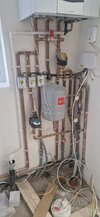
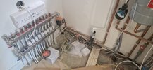
I recently got a new boiler installed and wanted to get a second opinion on whether this installation is correct.
Of course the installer was FGAS certified and therefore should be fine, but after going down a rabbit hole and realizing he hasn't added things such as weather/load compensation and left the condensing boiler running permanently at 70C I am not so sure anymore.

One concern I had was that since there are 3 pumps in this system, shouldn't there be some form of hydraulic separation? I can't see where this would be and from what I have read online this would be achieved with either a low loss header or close coupled tees.

Another was that there is a Altecnic ERED Bypass Valve under the boiler which seems to always be open - both sides are hot whenever the CH is running. Is this expected?

I hope I am overthinking it and that all my above concerns are just from my lack of understanding but any advice would be appreciated. The installer of course says everything is fine. (The wiring is not yet cleaned up so please ignore that)

Thanks
 

Attachments

  • WhatsApp Image 2025-01-20 at 13.49.04(1).jpeg
    WhatsApp Image 2025-01-20 at 13.49.04(1).jpeg
    167 KB · Views: 162
  • WhatsApp Image 2025-01-20 at 13.49.04.jpeg
    WhatsApp Image 2025-01-20 at 13.49.04.jpeg
    180.9 KB · Views: 139
Don't know why you've mentioned F-Gas, that's for air conditioning & heat pumps.

Yes, using Vaillant senso controls for weather or load compensation would be desirable, but are you prepared to pay the thick end of £1000 to add them to your setup? If it wasn't included in the original price, you can't expect it to be included in the installation either.

The two pumps in series are certainly incorrect. It's not unusual to see UFH manifolds connected the way yours have been although CCTs by the manifolds can help with circulation.

The bypass might just be suffering from conduction but it should be checked.
 
Apologies, I got F-Gas and gas safe mixed up.

I totally agree, it would be an added expense. However when I asked about Vaillant controls the engineer said it wasn't appropriate for this type of system and due to my lack of knowledge at the time I took his word for it.

Since the pumps in series are incorrect I will try to contact him again about this. Then I'll look at getting another guy to upgrade the system.

Thanks I appreciate the help!

(Also I should have mentioned the boiler is an ecoTec plus 635 system boiler, which seems to be extreme overkill)
 
The one on the radiator circuit would be unnecessary for most homes - the internal one in the boiler would do the job just fine on its own

After I posted, I had a look at this chart from the manual. If my maths is correct and I am reading the graph correctly (big if!!!), there is essentially zero residual head at full power of 35kW.

1737402977034.png
 
Apologies, I got F-Gas and gas safe mixed up.

I totally agree, it would be an added expense. However when I asked about Vaillant controls the engineer said it wasn't appropriate for this type of system and due to my lack of knowledge at the time I took his word for it.

Since the pumps in series are incorrect I will try to contact him again about this. Then I'll look at getting another guy to upgrade the system.

Thanks I appreciate the help!

(Also I should have mentioned the boiler is an ecoTec plus 635 system boiler, which seems to be extreme overkill)
635!? Wow, do you live in a castle? Sounds like it's your "engineer" who has a lack of knowledge as much as you do, and may also have broken Building Regulations which require a heat loss calculation to be carried out and a boiler no more powerful than is required according to that calculation to be installed.
 
After I posted, I had a look at this chart from the manual. If my maths is correct and I am reading the graph correctly (big if!!!), there is essentially zero residual head at full power of 35kW.

View attachment 370099
Yes, I'd agree with that, although the chances of this place actually needing 35kW based on what we've seen so far are minimal
 
635!? Wow, do you live in a castle? Sounds like it's your "engineer" who has a lack of knowledge as much as you do, and may also have broken Building Regulations which require a heat loss calculation to be carried out and a boiler no more powerful than is required according to that calculation to be installed.
Yh, I definitely didn't need a boiler that size -it's that old mentality of bigger is better. During house renovation the builder had boiler installation as part of his quote, and I made the mistake of not looking into what is required and trusting his gas guy would fit what was appropriate. I'll look into the heat loss calculation and building regulations you mentioned. I'll also ask by building control surveyor hopefully he will have some knowledge on this.
 
Last edited:
That pipe is a spare loop for the UFH. Should he have sealed it off differently? I guess just like the boiler he got a bigger manifold than was required o_O
 
After I posted, I had a look at this chart from the manual. If my maths is correct and I am reading the graph correctly (big if!!!), there is essentially zero residual head at full power of 35kW.

View attachment 370099

Yeah, that makes no sense to me, but if you look at my attachment/calcs, it looks like you would have around a residual head of 1.99M (pump at 100% speed), at the boilers rated flowrate of 1305LPH, 21.75LPM, not a lot, but obviously the residual head increases with reducing flow demand as the pump head increses and the HEX pressure loss decreases = greater residual head, for example at a typical flowrate, like mine, of 1000LPH, 16.67LPM, the pump head is 5.71M, Hex loss, 1.56M, residual head a fairly healty 4.15M?.

These boilers are dispatched in (pump) constant pressure mode set to 200mbar, 2.0M, for some reason or other, a fairly modest flow demand of 800LPH, 13.33LPM, Hex loss, 1.0M, residual head (at a 2M constant pressure), 1.0M, not much use. The max constant pressure setting is 400mbar (4.0M) and the minimum, 100mbar, 1.0M, so this mysterious graph seems to have something to do with this.
The second Vaillant graph in my attachment (Residual head) makes perfect sense as my graph (based on a 6M pump, matches it pretty well I thnk.

These boiler pump modes can also be set to fixed speed and temp spread dT mode, I'm assisting someone with 630 boiler which only runs properly in the fixed speed mode.
 

Attachments

If you need to find a tradesperson to get your job done, please try our local search below, or if you are doing it yourself you can find suppliers local to you.

Select the supplier or trade you require, enter your location to begin your search.


Are you a trade or supplier? You can create your listing free at DIYnot Local

 
Back
Top