Laying 33m of soil pipe over land which is 4.5° slope

Joined
24 Jul 2008
Messages
10
Reaction score
1
Location
Yorkshire
Country
United Kingdom
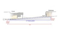
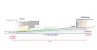
Hi, I need to lay a new soil pipe system approx 40m distance across land which is about 5° natural slope [downwards].
What is the best way to achieve 1:40 [about 1.4°] fall over such a long distance?
There are no buildings in the way but it needs to go under a driveway track.
I want to minimise any visual inspection chamber lids as it is a garden area.
Cheers!
 
You want to achieve 1:40 fall over the 40m run? If you can have the trench left open, then 10m at a time could be laid, ensuring you've 250mm of fall across the 10m, using a string line and spirit level. Set some bricks at the required height to sit the pipe on, then bed with peagravel, and remove bricks once the gravel is supporting the pipe.

Boning Rods are another option, there are various instructional videos available, but might be a bit tricky if you've not set them up before. Ditto a Laser.
 
I guess 1m drop over 40m may not be such a deep trench. Depends on culvert depth of where it discharges.
 
I guess 1m drop over 40m may not be such a deep trench. Depends on culvert depth of where it discharges.
Yes, you're right. I will need to measure back from the final discharge site.
FYI, this is an offgrid location where the waste water is processed through a treatment plant which outputs to a nearby gulley. The gulley will have 4 swale features along its length to slow the water down as it travels towards the stream.
Another factor is that the house is built on stilts and a nearby workshop is a concrete slab. The workshop [which includes a toilet] is the highest point on the land.
The land is generally sloping approx 4.5° [see section image].
*** Its actually around 33m, not 40m ***
Nothing is built as yet, screws for the house are going in shortly.
Thanks,
 

Attachments

  • Soil pipe schematic - Landscape image.jpg
    Soil pipe schematic - Landscape image.jpg
    626.3 KB · Views: 42
  • Soil pipe schematic 02.jpg
    Soil pipe schematic 02.jpg
    59.6 KB · Views: 39
Last edited:
Ah, so you're going to need attenuation tanks.
No, not for rainwater control. The rainwater from the workshop will run into the natural ponds with overflow to the stream. Rainwater from the house will collect in 3 IBC's then overflow to the gulley.
My main issue is working out how many and where the inspection chambers go, to give me 1.4° fall on the waste...
 
My main issue is working out how many and where the inspection chambers go, to give me 1.4° fall on the waste...

Not sure what you're trying to achieve? Regs allow for a straight run of drainage up to 100m between Chambers, 33m can be done in one run, provided its straight. Fall needs to be on the pipe, if using plastic chambers, then they should be set level, a slight fall is built in. Chambers are only needed at a change of direction or a sudden change in Invert Level, where a Ramp or Backdrop would be used.

As an aside, bear in mind a Tanker will need to access the Treatment Plant for periodic desludging.
 
Apologies for not being clear.
The 1.43° is 1:40 fall, which I believe is the max allowed. The green line on the attached sketch shows how it will break ground in front of the house... so I guess I will just have to add another backdrop chamber to keep the pipe in the ground?

Regarding the desludging for the treatment plant - I would expect that a vehicle could go further along the track and reach the treatment plant with an extending pipe [its probably only about 20m from the track.

Thanks
 

Attachments

  • Soil pipe schematic 03.jpg
    Soil pipe schematic 03.jpg
    64.1 KB · Views: 25
Apologies for not being clear.
The 1.43° is 1:40 fall, which I believe is the max allowed. The green line on the attached sketch shows how it will break ground in front of the house... so I guess I will just have to add another backdrop chamber to keep the pipe in the ground?

Regarding the desludging for the treatment plant - I would expect that a vehicle could go further along the track and reach the treatment plant with an extending pipe [its probably only about 20m from the track.

Thanks
Not my field, but from memory I thought the minimum fall was 1:100. Didn't know there was a maximum, can't see why there would be.
 
Minimum gradient for 100 pipe with 1 WC connected is 1 in 80 on the assumption that peak flow exceeds 1l/s, if flow is less than 1l/s minimum recommended gradient is 1 in 40. No maximum as such but as stated there is a thought that if the gradient is to great debris can get left behind but then again another thought is the next flush pushes/rolls it a long especially if its just a number 1 flush or, say, emptying bath/sink/shower
 
According to Floplast
' "There is no maximum gradient; a fall of 1:10 is usually considered as a maximum guideline. BS8301 states “Research has shown that high velocities of sewage flow arising from steep gradients do not cause increase erosion of pipes or deposition of solids.” '

News to me, I always thought 1:20 to 1:80 were the limits.
 

If you need to find a tradesperson to get your job done, please try our local search below, or if you are doing it yourself you can find suppliers local to you.

Select the supplier or trade you require, enter your location to begin your search.


Are you a trade or supplier? You can create your listing free at DIYnot Local

 
Back
Top