Doorbell transformer broken? Or worse issue?

Joined
31 Dec 2019
Messages
53
Reaction score
2
Country
United Kingdom
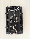
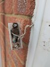
Hi all, recently tried to change my parents old manual doorbell to a reolink video one. As per instructions, I jumped the chime cables, switched the new doorbell and gave it a try. It didn't work so I reverted everything back. Only to find out the old doorbell now didn't work.

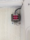
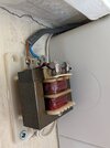
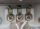
I then decided to purchase a multimeter to test the transformer. upon testing, there was no reading at the transformer (200v setting on the bottom terminals and 600v at the top/input).

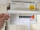
I've tried resetting the main fuse box (left one and entire board) but no improvement. Any ideas on what to do next please?
 

Attachments

  • PXL_20260829_124051026.MP.jpg
    PXL_20260829_124051026.MP.jpg
    349.3 KB · Views: 25
  • PXL_20260829_133134854.MP.jpg
    PXL_20260829_133134854.MP.jpg
    251.1 KB · Views: 24
  • PXL_20260829_133137597.MP.jpg
    PXL_20260829_133137597.MP.jpg
    251.5 KB · Views: 26
  • PXL_20260911_111659087.jpg
    PXL_20260911_111659087.jpg
    340.3 KB · Views: 23
  • PXL_20260911_111900229.jpg
    PXL_20260911_111900229.jpg
    345.5 KB · Views: 23
On a quick read you probably shorted the transformer and it needs replacing

I'm not too familiar but those video doorbell manuals i think do a "one size fits all " install method of shorting at the doorbell to bring a supply to front door which doesn't apply in all cases
 
From memory 0 and 3 are the coil, and 1 and 2 are parking terminals if not using batteries and are to the door push when using batteries.

So one wire to 2 is wrong, with no batteries if 1 or 2 is used, it will have 2 wires.

So line 1 from transformer to 0 and line 2 to either 1 or 2 where it connects to one door push wire, and the other door push wire to 3.

The old doorbell worked on 6 volts DC and a higher voltage AC seem to remember 8 volts, been a while since used one. Most video doorbells seem to use DC and a higher voltage around 12 volts.

The transformer is clearly AC, and it does seem to have options as to voltage 1789213607363.png often 3 options, like 4, 8, and 12 volts, but AC so what does the new doorbell say is needs?
 
From memory 0 and 3 are the coil, and 1 and 2 are parking terminals if not using batteries and are to the door push when using batteries.

So one wire to 2 is wrong, with no batteries if 1 or 2 is used, it will have 2 wires.

So line 1 from transformer to 0 and line 2 to either 1 or 2 where it connects to one door push wire, and the other door push wire to 3.

The old doorbell worked on 6 volts DC and a higher voltage AC seem to remember 8 volts, been a while since used one. Most video doorbells seem to use DC and a higher voltage around 12 volts.

The transformer is clearly AC, and it does seem to have options as to voltage View attachment 422187 often 3 options, like 4, 8, and 12 volts, but AC so what does the new doorbell say is needs?

With the doorbell chime. I've just wired it to the original wiring when it was still working.

With the transformer, I will try and wire the middle white wire to the left terminal?

Will need to work out why multimeter is coming back with zero tho
 
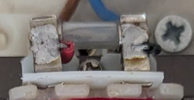
Well spotted View attachment 422188 looks like time to get soldering iron out.
No need for a soldering iron to replace a glass (20mm likely) fuse in a skeleton fuseholder... Ceramic sand-filled would be better for a mains fuse... if the same Amps and Time rating can be found.

Those may be stamped on the ends of the current fuse. ISOLATE the mains before touching that fuse though!!
 
Correct wiring:
1789217486286.png


However this will not correct it if the transformer has failed/fuse blown.
With the doorbell chime. I've just wired it to the original wiring when it was still working.

With the transformer, I will try and wire the middle white wire to the left terminal?

Will need to work out why multimeter is coming back with zero tho
Was your meter set to AC volts?
 
Correct wiring:
View attachment 422191

However this will not correct it if the transformer has failed/fuse blown.

Was your meter set to AC volts?

Are you sure? I could have sworn the wrong in my photo was what's there originally (thought I had taken the photo before touching it).

P.s. mystery just solved. Realised multimeter AC was faulty - I did a DC check to see if wires were working but didn't actually check AC. Got it working now so will go back to site and test the transformer later.

But would be good to understand if the chimes wiring is correct
 
Are you sure? I could have sworn the wrong in my photo was what's there originally (thought I had taken the photo before touching it).

P.s. mystery just solved. Realised multimeter AC was faulty - I did a DC check to see if wires were working but didn't actually check AC. Got it working now so will go back to site and test the transformer later.

But would be good to understand if the chimes wiring is correct
If you look at this pic - but ignore the moulded numbers (I've added your in red) and white wiring as it is used differently to yours - you can see the copper solenoid wires arrowed.
1789221914854.png
If you can see the copper wires in your chime and they are not going to the same locations arrowed then feel free to come back and ask again.


What you need to achieve is is a closed circuit which the current can flow round, like this:
1789222512274.png

It doesn't matter if the transformer and bell push are transposed or where each of the 3 components are within the ring, for example if you find the solenoid is unusually on terminals 1&2 is will be something like this:
1789223710316.png
 

If you need to find a tradesperson to get your job done, please try our local search below, or if you are doing it yourself you can find suppliers local to you.

Select the supplier or trade you require, enter your location to begin your search.


Are you a trade or supplier? You can create your listing free at DIYnot Local

 
Back
Top