Not quite. The Drayton is removed and the Nest Heat link replaces it and it will take the now unused N & L from there. So...
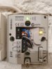
...The Drayton wire connections can be identified from the diagram on the back of it. This has the wires that control both the central heating and the hot water.
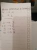
Based on the above diagram / photo, the wires move from the Drayton to the terminals that have exactly the same function at the Nest Heat link. So,
The blue wire in Drayton (N) goes to Heat Link (N)
The brown wire in Drayton (L) goes to Heat Link (L)
The black wire in Drayton (3) HW ON goes to Heat Link (6) HW call for heat
The grey wire in Drayton (4) CH ON goes to Heat Link (3) Heating call for heat
Then the two Heat link common terminals (2) and (5) should be wired / linked to terminal (L)
The Nest thermostat requires 12v power for it to operate. This can be provided by running a new cable to connect terminals T1 & T2 at the Heat link, to the corresponding T1 & T2 terminals at the Nest thermostat. If you do this you will also need an earth connection to the earth terminal next to T1 & T2. Alternatively the Nest thermostat can simply be powered by a separate plug in power supply.
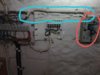
To remove the old thermostat find the origin of the brown and grey wires in this cable that you have highlighted...
...where they terminate at the wiring centre on the left in your photo. Note where they go, and then remove the old thermostat cable and the old thermostat receiver completely. Then join together the two terminals where you have just removed the brown and grey wires from.
PLEASE NOTE:
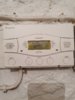
The photo below is not 100% clear. To me it looks like black wire in LX is simply a loop of wire connecting LX and L. And the above instructions are based on that assumption. If this is not the case, and the black wire in LX goes somewhere else, don't proceed and post back details of where it goes.


")