• Looking for a smarter way to manage your heating this winter? We’ve been testing the new Aqara Radiator Thermostat W600 to see how quiet, accurate and easy it is to use around the home. Click here read our review.

Room Thermostat wiring help needed...

Joined
1 Dec 2025
Messages
3
Reaction score
2
Country
United Kingdom
Hi all,

I am trying to replace my antiquated TLX SUNVIC (circa 1978) room thermostat with a Honeywell MT1 (THR830T)

I am a bit puzzled by the wiring though, as I thought it would be a straight like for like... can anyone help please?
See pictured below existing wiring vs wiring in mew thermostat.
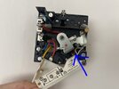
When measuring with meter, it seems Blue has no voltage whereas Yellow and Red are live.

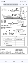
Also, according to the SUNVIC diagram, the yellow (open) cable goes to 1 on old thermostat, whereas in my case it was connected to 2 (close), and the blue goes to Neutral whereas in my case it was connected to 1 (open)...
Does this imply that in my case blue is open, yellow close and there is no neutral?
Is there way I can verify this using meter so nothing goes Kaboom?

Original wiring:
IMG_8385.JPG


and Sunvic diagram:
1764582794787.png


New wiring (doesn't work):

IMG_8402.JPG


wiring diagram for new Thermostat:
IMG_8387.jpg


Help greatly appreciated.

Thanks
 
The old mechanical thermostat does not need a neutral, by using the neutral the droop can be reduced, but it is not needed. It would seem the old thermostat is designed not to use a neutral, the new old is designed to use the neutral to reduce the droop (difference between on and off temperature).

So
3 Sunvic to 1 Honeywell
1 Sunvic to 4 Honeywell
2 Sunvic to 3 Honeywell

I have never seen a motorised valve which is powered in both directions, I am sure they did exist, but today the motorised valve is powered all the time it is open, and it is designed to work 24/7 stalled, and it has a micro switch that turns on the boiler, so boiler does not fire until valve is open. I found this advert which does explain the valve
Years of experience in the mastery of valve design and manufacture gives uniqueness to the products within our range.
more here not a clue why it does it that way, until I looked it up, did not even know it existed. I note a resistor shown between 2 and 3, not sure how not having it will change how it works.
 
Am I wrong, but may be the other red is Neutral with a possible blue sleeving? Hard to tell exactly from the photo. Also a black mark higher up or an I reading into too much?
 

Attachments

  • Screenshot_20251201-122927.png
    Screenshot_20251201-122927.png
    295.1 KB · Views: 7
Am I wrong, but may be the other red is Neutral with a possible blue sleeving? Hard to tell exactly from the photo. Also a black mark higher up or an I reading into too much?
That doesn't make sense.
I don't see any blue sleeving.
I think that red is part of the thermostat.

It is this diagram:
1764592838660.png


but terminal 3 is Live - Red - in all the diagrams
 

Attachments

  • IMG_8385~2.JPG
    IMG_8385~2.JPG
    253.7 KB · Views: 8
Last edited:
If the NC is not needed then the wiring could be rearranged at the other end of the cable to include Neutral.
I do wonder if the SUNVIC motorised valve actually fitted?
Am I wrong, but may be the other red is Neutral with a possible blue sleeving? Hard to tell exactly from the photo. Also a black mark higher up or an I reading into too much?
I was at first thinking the same, until I realised this is a unique valve type,

1764593238198.png
1764593272369.png

These diagrams show how these valves work, it is motored off and well as on. I have never seen one of these 1764593467789.png in the flesh so to speak, seems a good idea, but twice the price of normal valve.
 
Attached photo.
I still think that is part of the thermostat internal wiring.

I can't see any coloured diagrams, only black and white. Ok, no worries, must have looked at the wrong diagram, apologies.
There aren't any coloured diagrams. I only added "Red" because that is the colour used by the OP to terminal 3.

Still can't see any blue sleeving.
 
I have never seen a motorised valve which is powered in both directions, I am sure they did exist, but today the motorised valve is powered all the time it is open, and it is designed to work 24/7 stalled, and it has a micro switch that turns on the boiler, so boiler does not fire until valve is open. I found this advert which does explain the valve

MOMO, Motor on, motor off. I got fed up with replacing my failed 3-ports spring return actuator, almost an annual task. I heard about MOMO valves and actuators, and so decided to swap, and give one a go. So far, much more reliable, no failure at all, though (as I have always done) - I do keep a spare head to hand, just in case.

Difference is - old spring return actuator, is under constant stress from the spring, when open, the motor has to be powered, but stalled, generating heat.

MOMO actuator has no springs, much less strain on it, and the motor is only powered when the valve position needs to be changed. Difference is, just a few electronic components. Unlike the spring return, the MOMO is only able to rotate in one direction, and the water valve, has to match the actuator.

I was so wound up with the unreliability of spring return actuators. I was looking to design my own version of a MOMO.
 
Last edited:

If you need to find a tradesperson to get your job done, please try our local search below, or if you are doing it yourself you can find suppliers local to you.

Select the supplier or trade you require, enter your location to begin your search.


Are you a trade or supplier? You can create your listing free at DIYnot Local

 
Back
Top