Hi,
In my living room I have a double light switch that controls the living room light. On the other side of the living room door I also have a double light switch that controls the light in the living room. They are both double switches and yet they only turn on one light.
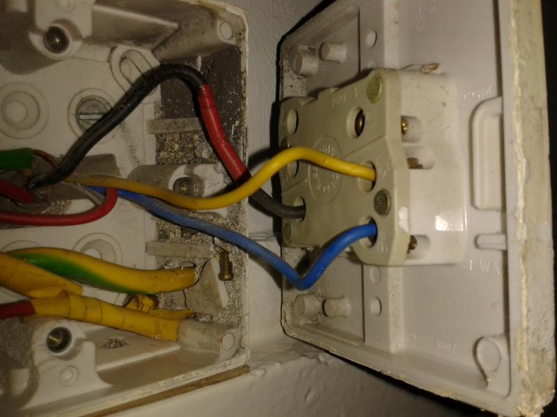
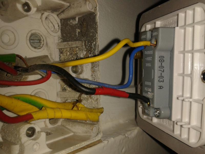
So I've bought 2 two-way single switches to replace them, but I have no idea how to wire them up because it looks like they've been wired in a 3 way set up?
Any ideas would be good, I've attached the wiring of the switches as they were before I took them off the wall.
In my living room I have a double light switch that controls the living room light. On the other side of the living room door I also have a double light switch that controls the light in the living room. They are both double switches and yet they only turn on one light.
So I've bought 2 two-way single switches to replace them, but I have no idea how to wire them up because it looks like they've been wired in a 3 way set up?
Any ideas would be good, I've attached the wiring of the switches as they were before I took them off the wall.

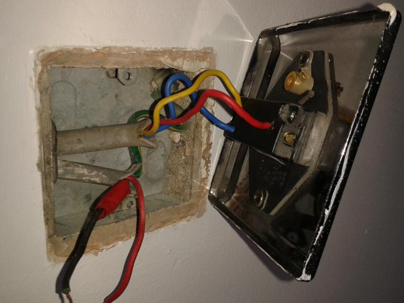
 There could still be a live supply connected to the switch wires from elsewhere, depending upon how it was wired in the first place. It would be good if you don't plan to use it, to have the circuit disconnected properly. As a minimum the wires at the switch should be insulated in separate screw connectors. EFLImpudence is correct, the metal faceplate also needs to be connected to earth