Hi everyone,
I'm looking to replace an old 4-gang dimmer switch with just normal switches but after loosening the faceplate, the wiring has me slightly confused.
When I've done this in the past it has usually been fairly straightforward and I would just replicate exactly this in the new switch, however this time I want to make sure I understand why this is wired as it is, before I touch anything else..
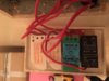
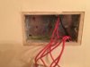
- Firstly all the wires into the back of the dimmer switches are red (picture 1). Is this right? There is one black (which runs straight through the back box - see picture 2), and the earth of course.
- Secondly there appears to be a couple a 'jumper' wire running between switch one L2 and switch 2 C. All switches are one-way by the way.
- The two white dimmer modules on the left don't seem to have any markings for C, L1 or L2, how do i know which wire is which?