500 amp mains intake

Joined
27 May 2010
Messages
9
Reaction score
1
Location
Suffolk
Country
United Kingdom
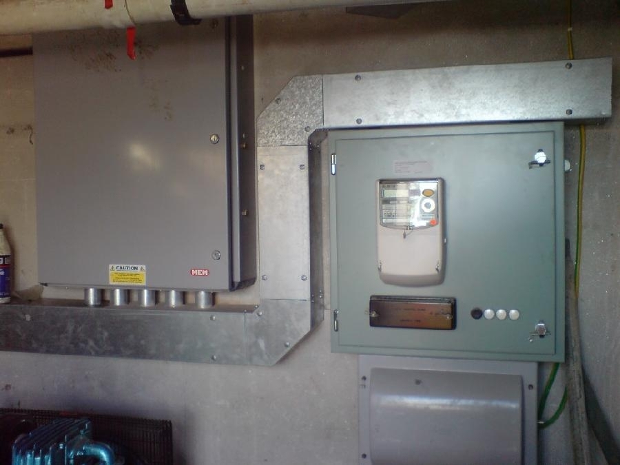
I am currently on a job where we are due to have a 500amp 3phase mains installed by the electricity board
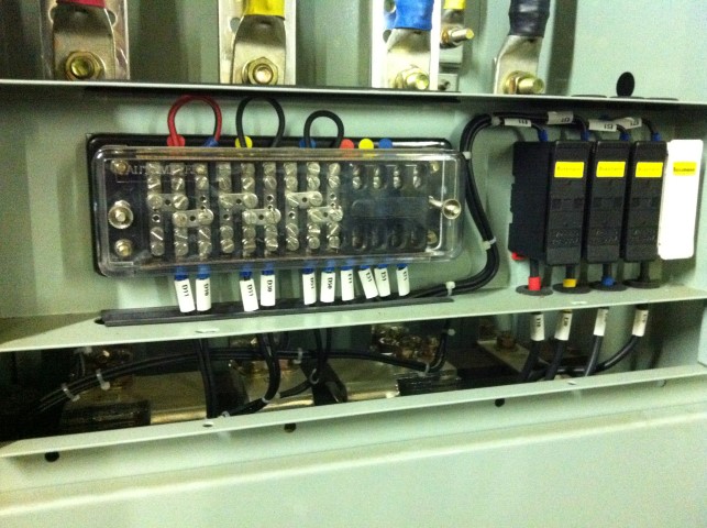
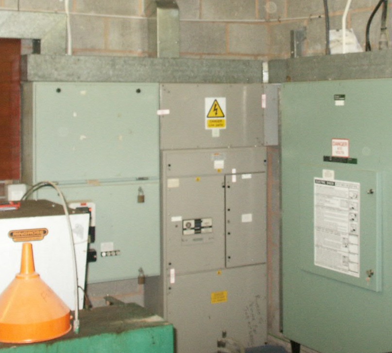
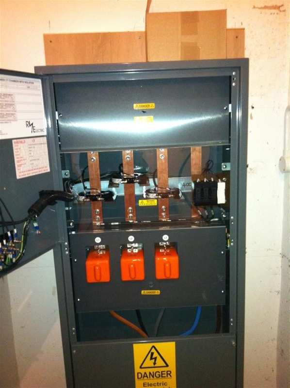
What sort of head would this normally be iam guessing it's not going to be a standard 3phase head and meter. Iam not doing any of the big boards, a work mate is but just got me thinking what it would be like. Iam guessing ct coils etc
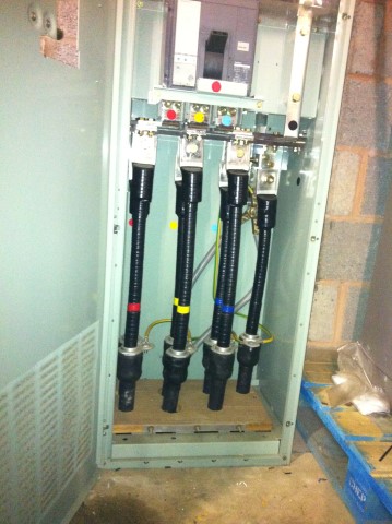
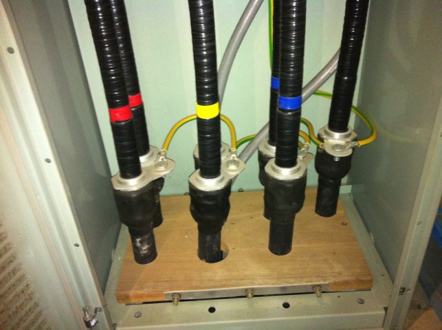
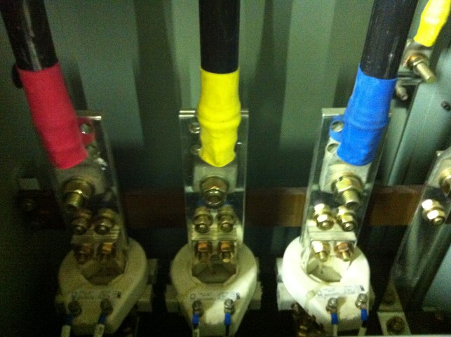
Anyone have any pictures of a 500amp incomer.
 
Sponsored Links
For that sort of load we would be looking at 4 x 400mm singles direct from a substation into the customer's LV switch gear. The metering CT's would be in the substation with installation and ownership of the singles resting with the customer.
Certainly the largest 3ph cable we use is not rated that highly nor any cable termination we use.

Having said that each DNO has it's own procedures so things could be different where you are
 
Older 500amp incomer with ACB, operated by a castell key. Grey cabinet is incomer and ACB, CTs in top of grey cab. Green cabs have metering fuses, top green cab is actually empty. Customer tails or matching busbar chamber bot to too busbar chamber.

1271521051.jpg


400amp recent incomer. Built in CTs etc, meter fits to front. Fused, no ACB. Customer tails lug to top busbar.

1299226532.jpg


1200amp incomer used at 800amp. ACB incomer, CTs and metering fuses in large cab, just metering in right cab. Customer tails lug to top busbars.

1271521695.jpg


200amp incomer. CT chamber sat on top of a Lucy service head. Customer tails through cab into service head.

1264609961.jpg
 
Sponsored Links
All the above are WPD. They don't CT meter anything in the sub, unless HV metering at the RMU.
 
Found some photos of the inside of the 1200amp incomer (used at 800 amp). 400mm customer tails.

These were taken when the site went from LV to HV metering. The incomer was retained and ownership transferred.

1381385961.jpg


1381385962.jpg


1381385959.jpg


1381385964.jpg


Metering connections, left shorted by the meter operator when they remove the meter. No need really, as the links are across on the terminals. I think they did this as they actually sheared the screw off :evil: 
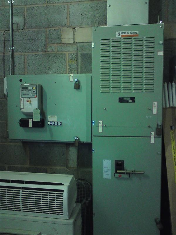
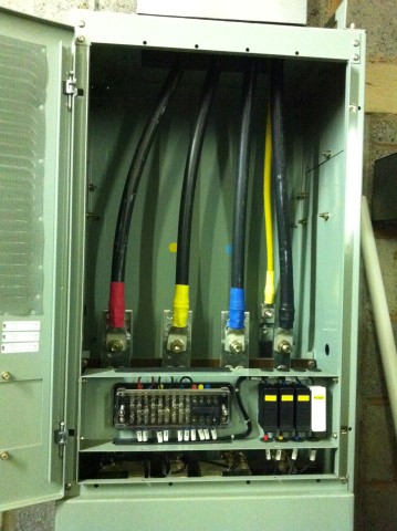
We have since put a meter back in place to monitor the difference between the HV and LV, which shows the 2.5% losses of the substation. There are reasons to do this for this company.

1381385966.jpg
 
Found some photos of the inside of the 1200amp incomer (used at 800 amp). 400mm customer tails. ... These were taken when the site went from LV to HV metering. The incomer was retained and ownership transferred.
Learning time for me! What are those G/Ys in the first couple of pics earthing/bonding/doing? - and (more-or-less regardless of that answer) why didn't they have to be sized more in keeping with the CSA of the live conductors?

Kind Regards, John
 
There are two thumping great DI tails in the back too - These are the customers TN-S earthing. Both in parallel.

The smaller earths are bonding the aluminium cable glands which are biting on the wave-con outer copper, also part of the TN-S earth.

The cables are actually 120mm (I think) 4 core aluminium conductor, but the 4 conductors in each cable are just stripped and shoved into the same aluminimum lug, acting as a single conductor (so 480mm). There are two of these in parallel for each phase, just the one for the neutral. This was all WPDs install, it's just been adopted. The other ends were pulled from WPDs sub and turned into a new privately owned GRP enclosure.

If you count the 7 120mm 4cores copper waveform outer, and the two 70mm (again, I reckon) DI tails, there is plenty of CSA. Not ideal just linking with the small earth on the glands though I guess.
 
There are two thumping great DI tails in the back too - These are the customers TN-S earthing. Both in parallel.
Yes I noticed them.
The smaller earths are bonding the aluminium cable glands which are biting on the wave-con outer copper, also part of the TN-S earth. ... If you count the 7 120mm 4cores copper waveform outer, and the two 70mm (again, I reckon) DI tails, there is plenty of CSA. Not ideal just linking with the small earth on the glands though I guess.
That last bit ("not idea") was really what I was referring to/asking about. The nature of earthing is surely such that any part of the 'network' of earth conductors can, under certain fault conditions, carry a 'full' fault current - which is why I was wondering about those 'tiddlers' in comparison with the CSA of the rest of the earthing system (and CSA of the live conductors).

Kind Regards, John
 
I would say that the earth links are the same size as the overall wave form CSA, but I guess you would then want to see a separate earth from each gland to a marshalling point.

I guess aslong as the DI earths satisfy that required by the adiabetic, then the smaller ones could almost be considered supplementary.
 
I guess aslong as the DI earths satisfy that required by the adiabetic, then the smaller ones could almost be considered supplementary.
It looks as if the DIs only go to one pair of glands - so doesn't that mean that fault currents from any of the others would have to go through the small G/Ys?

Kind Regards, John
 
We have installed something similar in the past, points to note are: -

The cable sheaths are only earthed at one end, usually the customer's

The neutral star point and the point at which it is earthed is in the panel, so the two large earth cables will be going to the earth rods

We class the cables up to the LV switch as part of the HV system/transformer winding, so any faults on them will only be cleared by the transformer HV protection.

The system we now use in these cases, sees parallel fuses (up to 3 x400A per phase) in our LV board controlling and protecting the cables to the customer's switchgear, as I said earlier the CT's would also be in our cabinet which makes the point of supply the outgoing terminals in our cabinet. In these cases the neutral star point is also there.
 
I guess aslong as the DI earths satisfy that required by the adiabetic, then the smaller ones could almost be considered supplementary.
It looks as if the DIs only go to one pair of glands - so doesn't that mean that fault currents from any of the others would have to go through the small G/Ys?

Kind Regards, John

The DIs come up out of the ground and upto the earth busbar.

Not sure if these cables have the earth done both ends. Can check. On site here Monday to fire up the backup genny for its three monthly full day on load run.
 
The DIs come up out of the ground and upto the earth busbar.
Oh - I thought there were hidden connections to one pair of glands. In that case, I think my prior question is perhaps even more relevent. Whatever purpose those small G/Y's are achieving, it seems (to ignorant little me!) a little odd that they should be so thin, given the magnitude of fault currents which could exist.

Kind Regards, John
 
If, as Westie suggests, the waveforms are earthed at just one end, no fault current would flow. Will see I guess....
 

DIYnot Local

Staff member

If you need to find a tradesperson to get your job done, please try our local search below, or if you are doing it yourself you can find suppliers local to you.

Select the supplier or trade you require, enter your location to begin your search.


Are you a trade or supplier? You can create your listing free at DIYnot Local

 
Sponsored Links
Back
Top