Hello. I've recently had a garage conversion. The spark has removed the old sockets/lighting and has rewired the new sockets and lights back to the existing garage consumer unit.

The consumer unit is fed from an old metal fusebox, which goes direct to the main CU in the house. The cable run start at the house CU in twin and earth, with an old junction box under the kitchen floor (I found this when running some cat 6 but wouldn't have expected the spark to). SWA then runs from the junction box under the floor to the old fusebox in the garage.
So I have:
House CU (32A MCB & 30mA RCD) > twin & earth > junction box under the floor > SWA > old fusebox > twin & earth > garage CU (32A & 6A circuits, also with 30mA RCD).


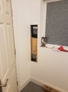
I don't see anything inherently unsafe in this set up, though it doesn't seem ideal (or necessary) having two 30mA RCDs & 32A MCBs in circuit. It also leaves a scruffy large space that will need a large door fitting due to allowing access to the garage CU and fusebox. As I have protection at the house CU could I ask the spark to terminate the SWA in a suitable small junction box with access still but in place of the metal fusebox. He could then also fit a FCU to supply the circuit for the lights?

TIA
The consumer unit is fed from an old metal fusebox, which goes direct to the main CU in the house. The cable run start at the house CU in twin and earth, with an old junction box under the kitchen floor (I found this when running some cat 6 but wouldn't have expected the spark to). SWA then runs from the junction box under the floor to the old fusebox in the garage.
So I have:
House CU (32A MCB & 30mA RCD) > twin & earth > junction box under the floor > SWA > old fusebox > twin & earth > garage CU (32A & 6A circuits, also with 30mA RCD).
I don't see anything inherently unsafe in this set up, though it doesn't seem ideal (or necessary) having two 30mA RCDs & 32A MCBs in circuit. It also leaves a scruffy large space that will need a large door fitting due to allowing access to the garage CU and fusebox. As I have protection at the house CU could I ask the spark to terminate the SWA in a suitable small junction box with access still but in place of the metal fusebox. He could then also fit a FCU to supply the circuit for the lights?
TIA