- Joined
- 5 Jan 2018
- Messages
- 16
- Reaction score
- 0
- Country

Hello,
I am after some advice on the wiring for the Heat Link for the Nest 3rd Gen. I have a S system with two separate 2 port valves for hot water tank and central heating.
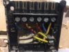
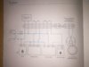
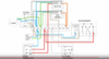
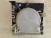
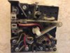
Please see attached photos for the wiring of my current programmer (acl Lifestyle Model LP522) and the S system wiring diagram for the nest.
As far as I can tell, I obviously need to put the live and neutral in the L and N ports on the Heat Link, then put the heating (currently port 4) into port 3 on the heat link and hot water (currently port 3) into port 6 on the heat link. Finally I need to bridge from live to port 2 and then to port 5 on the Nest Heat Link. Is this correct?
What is confusing me, is that there are currently two cables in the live port on my current programmer and a cable in port 2 (CH OFF).
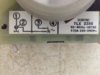
Finally, I currently have a Sunvic TLX thermostat on the wall in the hall which I'd like to wire into ports T1 and T2 on the Heat Link, but have no idea where these cables come out. Maybe it is best to just power the Nest Thermostat by USB and let it connect wirelessly only.
If you need anymore info, please let me know.
Cheers
Andy
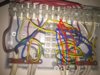
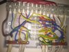
I am after some advice on the wiring for the Heat Link for the Nest 3rd Gen. I have a S system with two separate 2 port valves for hot water tank and central heating.
Please see attached photos for the wiring of my current programmer (acl Lifestyle Model LP522) and the S system wiring diagram for the nest.
As far as I can tell, I obviously need to put the live and neutral in the L and N ports on the Heat Link, then put the heating (currently port 4) into port 3 on the heat link and hot water (currently port 3) into port 6 on the heat link. Finally I need to bridge from live to port 2 and then to port 5 on the Nest Heat Link. Is this correct?
What is confusing me, is that there are currently two cables in the live port on my current programmer and a cable in port 2 (CH OFF).
Finally, I currently have a Sunvic TLX thermostat on the wall in the hall which I'd like to wire into ports T1 and T2 on the Heat Link, but have no idea where these cables come out. Maybe it is best to just power the Nest Thermostat by USB and let it connect wirelessly only.
If you need anymore info, please let me know.
Cheers
Andy