Nest 3rd Gen - wiring question

Joined
26 Dec 2016
Messages
2
Reaction score
0
Country
United Kingdom
Hi,

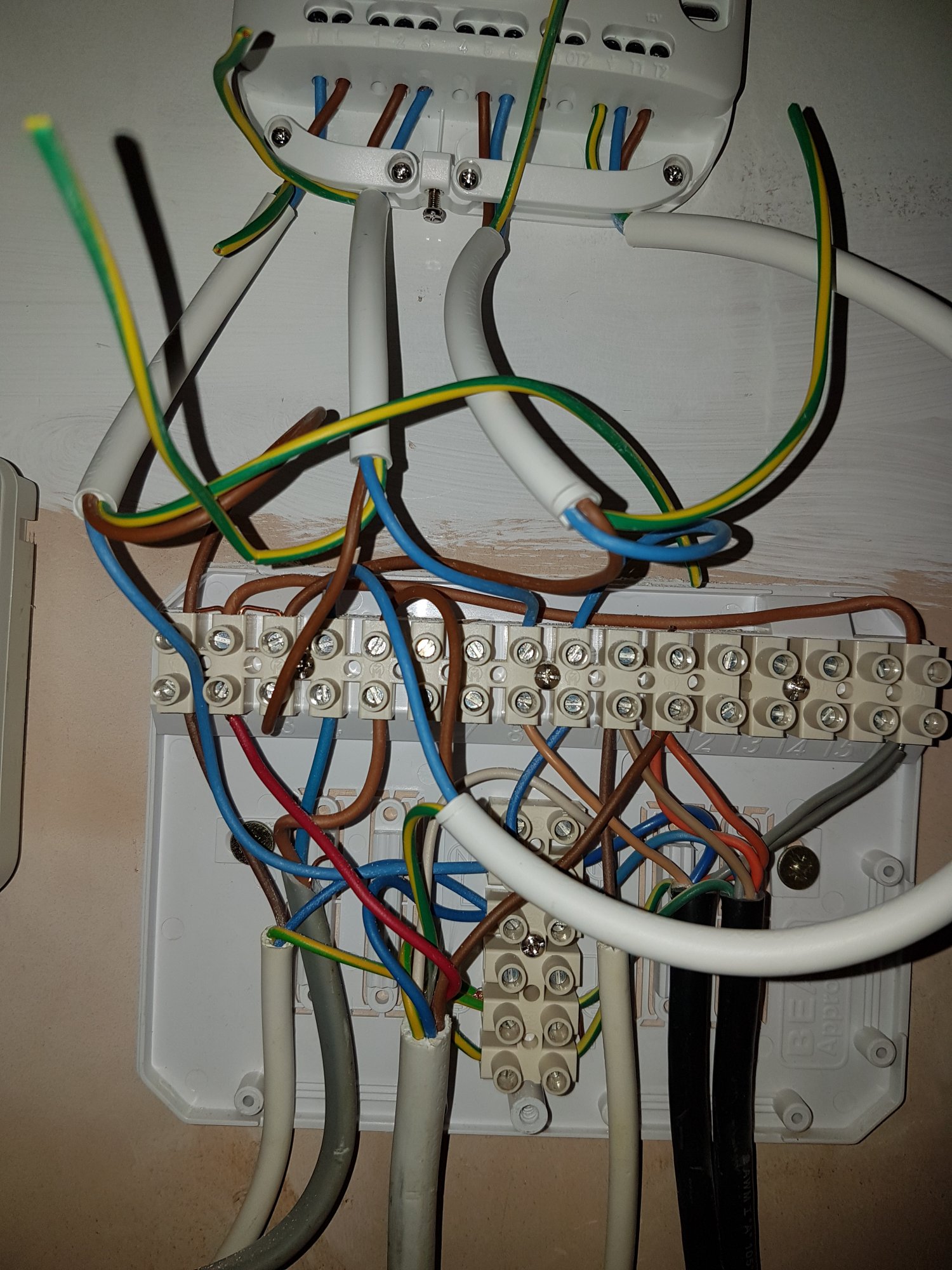
I have a Myson programmer installed - with a Honeywell T40 thermostat (connecting back to a Potterton Suprima 50L ... on my 3rd PCB in 10 years!!!!).

I'm looking to replace the Myson with a Nest 3rd Gen (UK with heatlink).

The Myson has live / neutral - and then the black and grey are wired to HW on and CH on respectively - no connection to CH/HW off.

Has anyone replicated this on a Nest 3rd Gen? If so, I'm keen to know how to replicate the wiring in the heatlink.

It looks to me like the first poster in this thread (//www.diynot.com/diy/threads/nest-3rd-generation-heat-link.468530/) had the same issue and wired L,N and then 3 (CH call for heat) and 6 (HW call for heat). Then ran a jumper from live to common for CH and HW (2 and 5).

Would that be right?

nest-booklet.jpg

I'm also guessing that if I unwire the old Honeywell T40 thermostat from the 230v box - I could install the Nest there and reuse the cables to power T1/T2 between that and the heatlink?

Advice appreciated.
 
Sponsored Links
The heatlink goes where the programmer is as you describe... L/N/3/6 and then you need to run T1/T2 from the heatlink to the actual Nest reusing existing wiring or go wireless between them.

Replicate what you've got now.

PS its boxing day im hammered.
 
Last edited:
The heatlink goes where the programmer is as you describe... L/N/3/6 and then you need to run T1/T2 from the heatlink to the actual Nest reusing existing wiring or go wireless between them.

Replicate what you've got now.

PS its boxing day im hammered.


Hahaha ... brilliant. Thanks for the input.
 
Sponsored Links
Hi can anyone provide any assistance on how I can wire up the heat link. I am having trouble identifying the live wire for the heat link plus the other two that need to be connected. This is a picture of the current set up.

Thanks in advance!
 

Attachments

  • 20170209_154856.jpg
    20170209_154856.jpg
    102.7 KB · Views: 292
  • 14866646180221602019404.jpg
    14866646180221602019404.jpg
    140.3 KB · Views: 360
De-wire the existing programmer in the wiring centre, then...


HL L into any of the the three terminals on the far left of the wiring centre (WC)

Link L, 2 & 5 in the HL

HL N into the second of the vertical set of terminals (common Neutral terminal), counting from the top, in the WC

HL Earth into the 6th vertical WC terminal (with the other earths)

HL 3 into WC terminal 8 and move the brown wire coming from the grey cable to terminal 5

HL 6 into WC terminal 9

HL T1 into terminal 4

HL T2 into terminal 5

Remove existing thermostat from the wall, use wires Brown & Blue to power your Nest, one in each terminal


That should do it, assuming nothing weird happens with your wiring out of sight!
 
Thanks for the quick advice!

Just to clarify the first 2 steps.

1. Heat link live into any of the 3 terminals on the far left.

So the live from heat link can be placed in numbers 1,2 or 3 on the WC?

2. Link live in 2 and 5 in HL.

So connect the live from WC above into 2 and 5 on heatlink?

Sorry just want to be clear!

Also is there any way of knowing if I have done it correctly?
 
Last edited:
Hi DBB and welcome to the forum.

As you started a 'conversation' directly with me yesterday, I wasn't expecting to then find the same question to appearing on the forum, already with input from others. However, as I had already gone to the trouble to put together a wiring diagram for you it is posted below.

As you have an 'S Plan' with two motorised valves and two thermostats (one each for the hot water and heating) it is impossible to be sure without knowing where each of the cables goes, to determine which is which. So, based on the types of cables used, I have assumed that the cable presently with wires in terminals 9 & 10 goes to the cylinder thermostat, and the grey cable with wires in terminals 4 & 8 goes to the room thermostat. If this is wrong ignore the diagram below and post back.

Also, I noticed that you have added your question to an existing thread started by dannyboy 1121. You should really have started your own new thread. What you have done is known as hijacking and is against the forum rules. This is because it causes confusion as it is not always possible to tell who is answering who's question. As you are a newbie and this is your first post, I hope you don't mind me pointing it out for next time.:)

Anyway. Here's your diagram, and as I said before, if my assumptions about which thermostat is which is wrong, post back and I will correct it. Also, if you let us know how you get on, it can help others who come across this thread when searching for information for a project of their own.

Nest Interconnections.jpg
 
Last edited:
Sorry Stem this is the first time I've used this forum so wasn't sure how active they were, but very pleased with the quick responses you both have provided. I've wired up the heat link if you could just have a look to see it if looks correct I would be most grateful.

Thanks

[/GALLERY]
 
OK, so assume my assumption regarding the existing wires was correct.

It looks OK to me. Nice termination of the wires, without lots of copper on show or wire whiskers poking out. I assume you will tidy up the unused earths and put the cable sheaths (not just the wires) under the cable clamps in the Heatlink and wiring centre.
 
Last edited:
Thanks Stem will do and many thanks to both you and Muggles for all your assistance with this I'm really grateful.
 
Last edited:

DIYnot Local

Staff member

If you need to find a tradesperson to get your job done, please try our local search below, or if you are doing it yourself you can find suppliers local to you.

Select the supplier or trade you require, enter your location to begin your search.


Are you a trade or supplier? You can create your listing free at DIYnot Local

 
Sponsored Links
Back
Top