Hi All
Apologies if this has been asked elsewhere I have trawled through the nest posts but cannot see anyone with a similar setup. I am currently trying to install the nest 3rd gen heat link box which replaces my old boiler programmer.
Here's what I have tried:
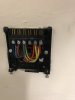
My old programmer had 4 wires going into it ( ) N/L/CH ON/DHW ON which I disconnected and connected to the nest heat link. (Bare with me as this is all new to me) The heat link gave me 3 options for both Heating and Hot Water (
 ) and I connected to the call for heat and call for hot water respectively (note my writing in the image is the wrong way round). The nest unit powers up and I can hear my wireless thermostat telling it to power the heating/hot water (click noise) but the boiler does nothing. I saw on another post someone using jumpers from live to common on both (
 ) should I be doing this? I am a complete amateur so I'm unsure about what the common or 'Satisfied (Optional)' do.
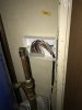
I have not touched my old thermostat which incidentally looks like this ( ) as the nest one works wirelessly off mains or 12V. Do i have to do anything to my old thermostat or will the new system render it useless, does it look like it has a 12v feed which I could use and replace it with the nest thermostat instead of using a plug?
Thanks again for any advice, i hope this all makes sense with my very basic knowledge. I have an electrician friend coming the weekend after next but hoped I could save him the trip and me some funds...
Apologies if this has been asked elsewhere I have trawled through the nest posts but cannot see anyone with a similar setup. I am currently trying to install the nest 3rd gen heat link box which replaces my old boiler programmer.
Here's what I have tried:
My old programmer had 4 wires going into it (
) N/L/CH ON/DHW ON which I disconnected and connected to the nest heat link. (Bare with me as this is all new to me) The heat link gave me 3 options for both Heating and Hot Water () and I connected to the call for heat and call for hot water respectively (note my writing in the image is the wrong way round). The nest unit powers up and I can hear my wireless thermostat telling it to power the heating/hot water (click noise) but the boiler does nothing. I saw on another post someone using jumpers from live to common on both () should I be doing this? I am a complete amateur so I'm unsure about what the common or 'Satisfied (Optional)' do.I have not touched my old thermostat which incidentally looks like this (
) as the nest one works wirelessly off mains or 12V. Do i have to do anything to my old thermostat or will the new system render it useless, does it look like it has a 12v feed which I could use and replace it with the nest thermostat instead of using a plug?Thanks again for any advice, i hope this all makes sense with my very basic knowledge. I have an electrician friend coming the weekend after next but hoped I could save him the trip and me some funds...