

I have looked through the various post on this site and whilst I've found a lot which are relative to my question, none of them really provide a direct answer.
I have a garage which currently has power for sockets and lighting. The garage is fed from a 40 amp MCB in the house CU via a 6 mm sq cable. This cable terminates into a second CU housing a main switch (no RCD) and two MCB's. One is a 20 amp for the sockets and the other is a 6 amp for the lights. (This is what I inherited when I bought the house. I had the house re-wired in 2005 and whilst the cable to the garage was not replaced, it was tested.)
I want to get power into my shed for an interior light and sockets plus to provide power for external lighting.
I am thinking of replacing the existing garage CU with one which will allow for expansion (say 5 way). Within this CU I would have an RCD (I am thinking 100 amps) I will then have a 20 amp MCB for the socket ring and a 6 amp MCB for the lights (as the existing). I will then add another MCB of 32 amps. This will be the for the shed.
I am thinking of running 2.5mm sq SWA from the 32 amp MCB to the shed (the cable will be buried in a trench).
Within the shed, I am proposing another CU which will have a 63 amp RCD. From this CU, I will run a ring for the sockets using a 16 amp MCB. (I have a pair of metal clad double sockets. they both have built in RCD protection and would like to use these to keep the costs down and to give extra protection.) I will add a 6 amp MCB for the interior light.
I also want to install exterior garden lighting operated by a remote control unit housed within the shed. There will be a total of five lights - one in each corner of the garden and a fifth illuminating a tree at the bottom of the garden.
Each of these lights will have its own 6 amp MCB and be fed via a 2.5 mm sq SWA cable. The reason for using individual MCB's is because the remote units I am thinking of using, only have a live and neutral. I obviously need to earth the armour of the cable and the light itself. In order to acheive this, I am thinking of terminating the SWA into a metal clad box with a blank cover. The armour will earth to the box via the gland. The earth wire of the SWA cable will terminate into the earth point of the box itself. In order to then continue the earth, I thought I could use a length of 2.5 mm sq earth wire (sleeved) which will 'daisy chain' from one metal box to the next. (there are five boxes in total) in the final box I propose to use a 4 mm sq earth wire which runs back to the shed CU earth.
I am thinking there will be a problem getting the shed earthed properly if I rely on the SWA feed into the shed (the cable length from garage CU to shed CU would be approx 25m). My thought process is, the earth will have to travel 25m to the garage CU and a further 15m (approx length of cable run) back to the house CU. To resolve this, I thought I could insert an earth rod outside the shed with a 16mm sq cable connecting this to the shed CU.
I'm sorry for the essay, but am trying to get all the information here.
In summary, here is what I am thinking: -
House CU 40 amp MCB - 6mm sq cable to garage - 5 way CU with 100 amp RCD - 32amp MCB - 2.5 mm sq SWA to shed - shed CU - 10 way CU with 63 amp RCD, with an earth rod in the ground outside the shed.
The exterior lighting will be 100w max. The shed sockets will only be running the lawn mower, strimmer, maybe rechargable power tools - essentially nothing with any great load to it. Obviously, the exterior lighting will be running at night and with the exception of the interior shed light, it is unlikely there will be any power taken from the sockets.
I am aware the will be some voltage drop but have no idea if the drop will prove too much for the set up I have in mind.
Is this acceptable? If it is belt and braces I am happy. If not suggestions please!!!!
I know all this would be notifiable and the reason for using a 10 way CU in the shed, a 5 way in the garage and 2.5 mm sq SWA between the garage and shed is because I already have them along with 6 metal clad blank boxes a rake of MCB's of varying amperages. I have amassed this kit over a number of years with a view to doing this work.
I think this installation is ok, my only concern is the existing 63amp RCD within the house CU.
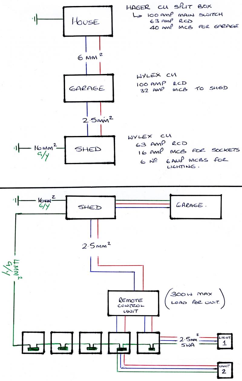
Having read through this post, I think some pics may help to clarify my intentions.
I have a garage which currently has power for sockets and lighting. The garage is fed from a 40 amp MCB in the house CU via a 6 mm sq cable. This cable terminates into a second CU housing a main switch (no RCD) and two MCB's. One is a 20 amp for the sockets and the other is a 6 amp for the lights. (This is what I inherited when I bought the house. I had the house re-wired in 2005 and whilst the cable to the garage was not replaced, it was tested.)
I want to get power into my shed for an interior light and sockets plus to provide power for external lighting.
I am thinking of replacing the existing garage CU with one which will allow for expansion (say 5 way). Within this CU I would have an RCD (I am thinking 100 amps) I will then have a 20 amp MCB for the socket ring and a 6 amp MCB for the lights (as the existing). I will then add another MCB of 32 amps. This will be the for the shed.
I am thinking of running 2.5mm sq SWA from the 32 amp MCB to the shed (the cable will be buried in a trench).
Within the shed, I am proposing another CU which will have a 63 amp RCD. From this CU, I will run a ring for the sockets using a 16 amp MCB. (I have a pair of metal clad double sockets. they both have built in RCD protection and would like to use these to keep the costs down and to give extra protection.) I will add a 6 amp MCB for the interior light.
I also want to install exterior garden lighting operated by a remote control unit housed within the shed. There will be a total of five lights - one in each corner of the garden and a fifth illuminating a tree at the bottom of the garden.
Each of these lights will have its own 6 amp MCB and be fed via a 2.5 mm sq SWA cable. The reason for using individual MCB's is because the remote units I am thinking of using, only have a live and neutral. I obviously need to earth the armour of the cable and the light itself. In order to acheive this, I am thinking of terminating the SWA into a metal clad box with a blank cover. The armour will earth to the box via the gland. The earth wire of the SWA cable will terminate into the earth point of the box itself. In order to then continue the earth, I thought I could use a length of 2.5 mm sq earth wire (sleeved) which will 'daisy chain' from one metal box to the next. (there are five boxes in total) in the final box I propose to use a 4 mm sq earth wire which runs back to the shed CU earth.
I am thinking there will be a problem getting the shed earthed properly if I rely on the SWA feed into the shed (the cable length from garage CU to shed CU would be approx 25m). My thought process is, the earth will have to travel 25m to the garage CU and a further 15m (approx length of cable run) back to the house CU. To resolve this, I thought I could insert an earth rod outside the shed with a 16mm sq cable connecting this to the shed CU.
I'm sorry for the essay, but am trying to get all the information here.
In summary, here is what I am thinking: -
House CU 40 amp MCB - 6mm sq cable to garage - 5 way CU with 100 amp RCD - 32amp MCB - 2.5 mm sq SWA to shed - shed CU - 10 way CU with 63 amp RCD, with an earth rod in the ground outside the shed.
The exterior lighting will be 100w max. The shed sockets will only be running the lawn mower, strimmer, maybe rechargable power tools - essentially nothing with any great load to it. Obviously, the exterior lighting will be running at night and with the exception of the interior shed light, it is unlikely there will be any power taken from the sockets.
I am aware the will be some voltage drop but have no idea if the drop will prove too much for the set up I have in mind.
Is this acceptable? If it is belt and braces I am happy. If not suggestions please!!!!
I know all this would be notifiable and the reason for using a 10 way CU in the shed, a 5 way in the garage and 2.5 mm sq SWA between the garage and shed is because I already have them along with 6 metal clad blank boxes a rake of MCB's of varying amperages. I have amassed this kit over a number of years with a view to doing this work.
I think this installation is ok, my only concern is the existing 63amp RCD within the house CU.
Having read through this post, I think some pics may help to clarify my intentions.

 ) The 16mm sq earth wire I also have here - although I only have about 4m.
