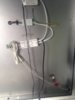
Can you just confirm, the lettering on the bottom white box is identical to this...
http://www.savemylight.co.uk/light-switches/sensor/hzk218c.html
...because you've managed to cover over a very important bit with the black cable, which is the "rated current"!

Anyway, I'm pretty sure these remote IR sensors are
not as simple as the three wires being 'positive', 'negative' and 'trigger'. I believe you would need an oscilloscope to be able to check for certain!

In which case, your best bet is to bypass that "electronic IR sensor switch" module altogether. This is how what you've got is wired up...
View attachment 158639
You would need to fit a pull switch rated for 250v AC and the correct Amps or higher. Then you'd need to extend the cables "Incoming power" and "Outgoing to LED driver" to where the pull switch is going to fit. "Cable to demister" will probably reach depending on how the cover/mirror is fitted, but that will also need to be connected to the pull switch, rather than where it is now. Cable "To LEDs" won't need to change at all.
The 3 neutrals you'll have will all connect together in a choc block. The two terminals on the pull switch will need the live from "Incoming power" in one of the terminals and both the live from "Outgoing to LED driver" and the live from "Cable to demister" will go together in the other terminal of the pull switch.


")