
I'm also thinking of a creating a wiring diagram for the system as it stands now and posting that on here.......

You are using an out of date browser. It may not display this or other websites correctly.
You should upgrade or use an alternative browser.
You should upgrade or use an alternative browser.
Central Heating Electrical Fault.
- Thread starter chadvandonkey
- Start date
I think my money is on damaged cabling between the boiler and cylinder.
As you are an engineer could you temporarily (but safely) run new cables between the two areas, possibly up the stairs etc and run that for a few days?
I don't think the electrician insulation tested them thoroughly, he needs to test each wire in turn with each other wire, and not just test them to earth.
Shame you are not closer to Kent.
Very good idea. Make sure you label everything: component, wire colours and terminal numbers, including in the junction box (say which end you start).I'm also thinking of a creating a wiring diagram for the system as it stands now and posting that on here.......
having had a fairly close look at the wiring in your older post, it appears there are 4 cores connected to the cylinder stat. Can you confirm this is the case or not as that would be most unusual, and if it is so, could well be the cause of your problem.
What type of junction box are you using ? 10 way choc block or one of the honeywell wiring centres ? last question do you know what contacts fused together in the cylinder stat ?
It's a choc block as per the link earlier in the thread
All I know is the cyl stat fused because it was stuck on i.e. no matter how hot the water got it would not stop the boiler.
I think my money is on damaged cabling between the boiler and cylinder.
As you are an engineer could you temporarily (but safely) run new cables between the two areas, possibly up the stairs etc and run that for a few days?
I don't think the electrician insulation tested them thoroughly, he needs to test each wire in turn with each other wire, and not just test them to earth.
Shame you are not closer to Kent.
This is my last hope at the monent but a 50m reel of 4 core is pretty expensive considering i'll never use it - but if that's what it takes no worries.
having had a fairly close look at the wiring in your older post, it appears there are 4 cores connected to the cylinder stat. Can you confirm this is the case or not as that would be most unusual, and if it is so, could well be the cause of your problem.
You are dead right, a brown, and blue and 2 blacks. Don't ask me why but both black cables were connected at both ends to make 1 wire - BUT this has now been replaced with a new piece of cable.
The two blacks used in one terminal is the lazy way, IE you dont need to find out which one is which.
You could buy 100m of 3 core flex and run two of em
(3 core is cheaper and your more likely to use it up).
Just looked at your picture again, you would need a lot more than 4 cores anyway
You could buy 100m of 3 core flex and run two of em
(3 core is cheaper and your more likely to use it up).
Just looked at your picture again, you would need a lot more than 4 cores anyway
The two blacks used in one terminal is the lazy way, IE you dont need to find out which one is which.
You could buy 100m of 3 core flex and run two of em
(3 core is cheaper and your more likely to use it up).
Just looked at your picture again, you would need a lot more than 4 cores anyway
Yeah it is but it's replaced with 3 cores now so all sorted.
There a 3 cables in 4 core that i'd need, 2 from programmer to t.box and 1 from room stat to t.box. Like I said earlier I have already replaced these with a temporary piece of cable run up the stairs but I only have enough for 1 run so each cable was swapped 1 at a time if that makes sense.
The plan now is to draw out the circuit diagram as it stands and get it posted then look at the temporary wiring job.
Right I've had a good look at this tonight and seem to have found a discrepancy but still no solution.
Looking at the diagram you posed the CH ON wire from the programmer should go to the Common of the Room Stat. On my system it goes to the ON terminal of the Room Stat not the Common. The actual Room Stat Common wires out to the white of the 3 way valve.
So I crossed the wires to give me CH ON going to Room Stat Common and Room Stat ON to valve white as per the diagram - and the main fuse blew instantly before anything powered up. The other wiring seems to check out but i'll have another look tomorrow with fresh eyes.
Now I am confused because it looked like an obvious wiring fault but it wouldn't even power up. Does this make any sense??
Draw a schematic... or at least what you think you have found so far;
Such as, from the top of the photo, L representing the Left Side, R representing Right;
L1. Pump Earth & 3 Port Earth
R1. Mains Earth & Clock Earth
L2. Pump Neutral
R2. 3Port Neutral, Mains Neutral & Clock Neutral
This will at least enable us to make more sense of what's there. The photos you have supplied are fantastic, but the Wiring Centre could have done with more.
Such as, I can't quite make out which Wire is our Mains and which is our Programmer? Where does our Room-Stat enter? obviously some wires are clear and visible, but its spaghetti junction in there.
I'd recommend a re-wire. It would take a clued-up engineer 20-30 minutes to label those wires and re-wire them correctly. So allow yourself a few hours
I always like to seperate my strips into 10, using 123 for Mains LNE, 4&5/7&8 for CH&HW, 6&9 for Links and 10 for Pump&Boiler... But that's just me.
I could always post a guide to how I do it, if your interested?
I have drawn out the circuit it just needs tarting up and scanning in. Ill get it sorted tomorrow hopefully.
Here is the circuit I have drawn from my system. I've not filled in the Live and Neutrals but they obviously go to the programmer and boiler.
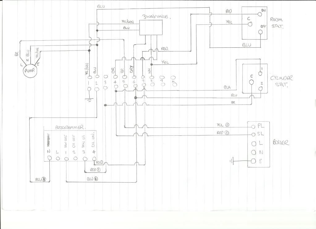
The small numbers after the wire colours from the programmer refer to wire 1 or wire 2 (the 2 wires that go from the programmer to the j.box upstairs)
DIYnot Local
Staff member
If you need to find a tradesperson to get your job done, please try our local search below, or if you are doing it yourself you can find suppliers local to you.
Select the supplier or trade you require, enter your location to begin your search.
Please select a service and enter a location to continue...
Are you a trade or supplier? You can create your listing free at DIYnot Local
Similar threads
- Replies
- 14
- Views
- 3K
- Replies
- 16
- Views
- 5K
- Replies
- 20
- Views
- 10K
- Replies
- 11
- Views
- 5K
- Replies
- 10
- Views
- 3K