Central heating not circulating - even after pump replacement

Joined
28 Oct 2013
Messages
46
Reaction score
1
Location
Hampshire
Country
United Kingdom
Had a few issues with our central heating system. A valve was getting stuck on, and the pump was getting increasingly noisy. It finally packed in and we lost hot water.

Simple job, I figured - replace the pump, might as well replace the valves while I'm at it. Had a load of trouble though. The valves were counterfeit (that'll show me buying from Amazon because it was cheaper...) but only realised after fitting.

My issue was, it just wouldn't circulate. The valves in manual override, and the pump pumping (making very slight vibrations at least). There was definitely water at the pump, as undoing the nut slightly caused a small leak.

But the boiler heated the water in it's immediate circuit - then it just stopped on the input side of the pump. I could feel the hot water on the left, and it was still cold on the right. The boiler turned off as no water was circulating for it to heat.

The valves for hot water and heating were manually set to open - so it's not any wiring issue. I tore the valves out (found out they were knockoffs) and checked and they DO open properly when set to manual - so can't have been that.

The pump valves were open, at least I checked them and set them to fully open before fitting. The pump is happily reporting no blockages.

Just... nothing is happening. I'm all out of ideas on what to check. My only thought is the brand new pump is defective... I can't see any other reason water wouldn't be flowing.

The hot water inlet didn't drain, so maybe it has a blockage or something in the pipework? But the heating drained fine - so I'd expect at least that to circulate.

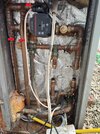
Here's the pump/valve layout, after having removed and tested the valves (heating left, hot water right):

IMG_20240519_115957.jpg

I'm curious if anyone knows what the third pipe from the pump outlet is - it has some kind of valve on it, with a twist head, that I haven't touched. But I'm curious what it is - some kind of thermostatic bypass?
 
Sponsored Links
1. Make sure both pump valves are fully open. If either spindle just turns without ever stopping it suggest that spindle is broken, probably with the valve closed.
2. Make sure both motorised valves are open. Don't forget that, when manually latched open, turning the system on is likely to close them as soon as power is applied.
3. If you have an F&E tank in the loft make sure that it is full of water. Also, with both motorised valves latched open, try draining the system partly and make sure water is flowing freely. If not, the feed pipe from F&E into the system may be blocked. This is particularly likely if you drained the system without cleaning out the F&E tank first, as you may have washed muck into the system.
4. Open any air vents to make sure air is expelled from the system, and bleed the radiators.

The object with the white twist cap is an automatic bypass valve. It links flow and return if the system pressure gets too high (e.g. hot water off and all radiators have TRVs which are closed) so the pump isn't working against a closed water circuit.
 
1. Make sure both pump valves are fully open. If either spindle just turns without ever stopping it suggest that spindle is broken, probably with the valve closed.
Pump valves were replaced, and I checked they were working before fitting - they're definitely fully open (screwed out).
2. Make sure both motorised valves are open. Don't forget that, when manually latched open, turning the system on is likely to close them as soon as power is applied.
Both motorised valves are manually set to open (this is the second set I've fitted, and they're Danfoss ones that have the removable head, so I can twist the spindle and see both are open) - also rules out any wiring issues.
3. If you have an F&E tank in the loft make sure that it is full of water. Also, with both motorised valves latched open, try draining the system partly and make sure water is flowing freely. If not, the feed pipe from F&E into the system may be blocked. This is particularly likely if you drained the system without cleaning out the F&E tank first, as you may have washed muck into the system.
Prior to draining I did bail it out and cleaned the tank (it was awful!)

I'm pretty sure the feed from it is unblocked, there was a whole lot of suction going through the tank when I knocked the float valve and it started filling it with the radiators spilling onto the carpet.

4. Open any air vents to make sure air is expelled from the system, and bleed the radiators.
This was definitely an issue. I had a lot of trouble with air-locks, this system seems terrible for refilling. None of the radiators would bleed at first, had to attach a hose and manually fill them up. But I've removed the air from all the radiators - downstairs and upstairs with a hose, and also the hot-water tank bleed valve. They're not pressurised and squirt water out so I'm confident the header tank is exerting some pressure on the system.

For a moment I thought it was working. The downstairs rads started to heat up a little. The pipes after the zone valves started to get hot.

But now, it seems to not be circulating again. While the pipes at the boiler after the motorized valves are warm the radiators, and the pipes feeding into the hot water tank are stone cold.

The only thing I can think that could possibly be wrong is the replacement pump has been faulty all along?

If the automatic bypass valve had broken... do you think that could cause a pump to break straight away?
 
Last edited:
Sponsored Links
Is the bypass pipework hot?
Not really.

Temp on the inlet of the pump (left) is ~ 47C (too hot to touch)
Temp on outlet of the pump (right) is ~40C (bit hot)
Temp at the open HW mechanical valve (right most valve, removed in pic) ~24C (slightly warm)
Temp at the open CH mechanical valve (centre/left, removed in the pic) ~30C
Temp at the overflow pipe (left, with plastic twist cap) ~23C

Thanks for the help.
 
What mode and setting is the UPS3 on?, can you post a photo of the running pump with the LEDs.
You could remove the pump head and inspect the ports and impeller for debris/sludge.
 
IMG_20240520_231903.jpg

Here's the UPS3 close-up. I've mostly been attempting it on the fixed speed setting at max (the old Grundfos was a constant speed and set to "3").

I did try switching it to constant pressure modes for a bit, but it didn't seem to change anything.

The centre screw seems to push in a bit and spin (turned it off to test that), and the pump feels like it's spinning - gently vibrating away making small tiny-bubble-going-through-pump type noises. It is supposedly self bleeding. There's definitely water to it as the screw leaks if I twist it slightly - a drip, not hiss.

I've ordered a pump spanner (managed to tighten the it on by hand, but I can't get it off!) so will remove it and give it an inspection tomorrow, see if it's stuck.
 
View attachment 343820
Here's the UPS3 close-up. I've mostly been attempting it on the fixed speed setting at max (the old Grundfos was a constant speed and set to "3").
The UPS3 is a very powerful pump and CC3 at 6.4M will generally lead to air ingress especially when the pump is starting and stopping, CC1 at 4.2M is probably quite adwquate, CC2 at 5.2M certainly should be more than enough as all the UPS3s CC curves are, in effect constant pressure at the sort of flow rates you require. CP2 at 4.5M is also a good choice, I have installed a few UPS3s for friends, set to this, on a clean system, PP2 at 3.8M is often a good choice.
I did try switching it to constant pressure modes for a bit, but it didn't seem to change anything.
As above.
The centre screw seems to push in a bit and spin (turned it off to test that), and the pump feels like it's spinning - gently vibrating away making small tiny-bubble-going-through-pump type noises. It is supposedly self bleeding. There's definitely water to it as the screw leaks if I twist it slightly - a drip, not hiss.
Didn't know there is/was a vent screw on these pumps.
I've ordered a pump spanner (managed to tighten the it on by hand, but I can't get it off!) so will remove it and give it an inspection tomorrow, see if it's stuck.
If you are talking about the pump connections then these certainly require a nip up with a spanner, I also use rubber gaskets.

Can you identify 1,2&3 pipe connections. Normal installation is......from the boiler flow, Vent, Cold Feed, Pump, (VCP system) with the vent and cold feed no more than 150mm apart.

When you do remove the pump ensure the pump impeller vanes are clear, stick a tie wrap through them, photo of my 28 year old Salmson, still working perfectly on removal.
 

Attachments

  • VCP.jpg
    VCP.jpg
    790.1 KB · Views: 29
  • Pump Impeller.jpg
    Pump Impeller.jpg
    165 KB · Views: 23
Last edited:
Removed some of the expanding foam to have a look at the thin pipe (1) and see if it joins anything else - but it just angles left and goes into the wall. I wonder if this could be the cold water feed from the loft? That seems to be the only 16mm pipe - but that doesn't seem to make sense with 3 being the output of the burner...

IMG_20240521_095215v2.jpg


2 similarly, just turns left and goes into the wall along with the hot water and heating outputs.

3 I believe is the output of the boiler. There are only two pipes that go into the boiler, 3 (which was hot) and the very bottom right (which was cool)

The other side looks like this, if it helps. It's an RDB burner:
IMG_20240521_095856.jpg


In summary, this is my understanding, but I may be mistaken, 1 and 2 I'm unsure about. I'm reasonably confident the boiler output (normally at the top) and boiler return (bottom, and the only other pipe going into the boiler). So from that it makes sense which is the HW and CH out. There are two other pipes, one connects to the boiler in - so presumably is the return from the CH or HW - but there's only one (might they join before coming to the boiler?) The other pipe (2) is a complete mystery to me. Comes out of the wall and connects to the boiler out, but before the pump? And would it make sense for the feed from the loft (16mm, so maybe 1) connect to the boiler out before the pump?
IMG_20240521_095145-labeled.jpg

No access on the other side - it's in the subfloor under a fitted wardrobe!
 
Is the pipework original?

Yes, I would think "2 unknown" is the vent and "1 unknown" is the cold feed, problem is the vent (and boiler flow) is turned down so the vent might be air locked.

If there is a PRV (pressure relief valve) on the boiler, top, if so, even though it may leak afterwards, turn the red knob slowly anticlockwise to vent it until water flows out.

I would then isolate the pump and remove it, slightly (crack) open alternatively the inlet and outlet valves to ensure both sides clear.

Then, maybe, replace the pump, open the valves, tie up the ball cock, ensure any motorized valves manually opened, drain down the system, connect a mains hose to the drain and very slowly refill the system until the feed and expansion cistern is at its normal level. shut off the mains filling, shut the drain , put the pump to CC1, 4.2M and see how you get on.

It is possible that the pump is kaput, these UPS3 do seem to suffer more than their fair share of failures but hard to see it failed straight out of the box.
 
Last edited:
Phew! Got it working. Thanks for all the help.

Ended up replacing the pump with a Wilo unit. Have to say, diagnosing issues with it is much easier. It has a button to enter venting mode, but also has two super useful things
- A flow rate readout (impressed it's not just calculated from the rotor speed or something, but actual flow rate)
- Error/warning codes for air in the pump

Refilled the system and found that while the boilers and HW circuit were all bled with no bubbles - there must have been some kind of air-lock in the return to the boiler as it was showing no flow.

First, I got the main bubbles out by loosening the pump connection. This allowed the vent mode in the pump to force through enough air to let the CH circuit start circulating.

Switching back to the HW circuit caused the pump to error again due to air. I had to repeat the process of switching between CH (pressure from the radiators seemed force the air out of the boiler?) then HW (introduced air back into boiler?) a few times before both are flowing.

Will have to give it a while and see if it keeps working.

Just read your comment to connect the hose to the drain - that may well have pushed all the air out and got around the problem. I'll definitely try that next time.

There was likely no issue with the UPS3, must just have been air.
 
The Grundfos ups3 has to be the worst pump on the market when trying to get air out & circulate. Had nothing but bother with them on open & sealed systems.
We've actually removed & refitted the old style pumps on boiler installs, removed the manual bleed screw & had systems back up & running within minutes ,
The auto venting just doesn't work.
We've lost multiple hours trying to vent systems , sometimes retuning to the job the following day , hoping that's its managed to clear the air.
worst design ever ,
Just give us back a pump with a manual bleed screw :unsure:
 
Phew! Got it working. Thanks for all the help.

That's great news.

Ended up replacing the pump with a Wilo unit. Have to say, diagnosing issues with it is much easier. It has a button to enter venting mode, but also has two super useful things

What model WILO did you install? and what mode and setting??
And what is the power and flow?? How many rads?

I installed a 6M Wilo Yonos Pico nearly 5 years ago in my OV system, they then only displayed the power but quite OK as I could/can read off the flow rates from the pump curves, the flow rate of course is very useful but it actually is just a calculated number. One can also incrementally change the pump head in 0.1M steps in both CP and PP modes, On my 10 rad, 8 with TRVs, I run in 4.6M PP mode which results in a 3.5M actual head at 22/24 watts but falls to 14/16 watts and around 2.5M as the TRVs throttle down.
- A flow rate readout (impressed it's not just calculated from the rotor speed or something, but actual flow rate)
- Error/warning codes for air in the pump

Refilled the system and found that while the boilers and HW circuit were all bled with no bubbles - there must have been some kind of air-lock in the return to the boiler as it was showing no flow.

First, I got the main bubbles out by loosening the pump connection. This allowed the vent mode in the pump to force through enough air to let the CH circuit start circulating.
I vented mine much the same way, I left the pump discharge loose, I didn't use the auto air vent.
Switching back to the HW circuit caused the pump to error again due to air. I had to repeat the process of switching between CH (pressure from the radiators seemed force the air out of the boiler?) then HW (introduced air back into boiler?) a few times before both are flowing.

Will have to give it a while and see if it keeps working.

Just read your comment to connect the hose to the drain - that may well have pushed all the air out and got around the problem. I'll definitely try that next time.

There was likely no issue with the UPS3, must just have been air.
I installed one of those in a friends house but only because he has 16 rads but I connected it up to one of those cheap £20 but accurate energy monitors which helped while venting and choosing the appropriate mode/setting.
 
Last edited:

DIYnot Local

Staff member

If you need to find a tradesperson to get your job done, please try our local search below, or if you are doing it yourself you can find suppliers local to you.

Select the supplier or trade you require, enter your location to begin your search.


Are you a trade or supplier? You can create your listing free at DIYnot Local

 
Sponsored Links
Back
Top