Changing Drayton LP 522 to Tado

Joined
31 Dec 2023
Messages
3
Reaction score
0
Country
United Kingdom
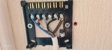
Hi, Changing my Drayton Lifestyle LP522 to a Tado, I am on a Y plan. On LP 522 backplate I have 5 wires,
N blue live Brown , 1 Grey, 3 Bk then on 4 an earth covered with a brown sleeve . I know this usually signifies permanent live so what do I do with it please, I was thinking it possibly goes to HW NO but don't want to risk blowing anything . I would really appreciate any help please.
 

Attachments

  • 104204-DIGITAL-WRB01IB01-INSTALLER_MANUAL-TA-EN-00-V3.pdf
    260.1 KB · Views: 47
  • 20231226_120410.jpg
    20231226_120410.jpg
    118.6 KB · Views: 45
  • 20231226_121808.jpg
    20231226_121808.jpg
    162 KB · Views: 48
Sponsored Links
Y Plan needs a N/C contact to turn DHW off when CH running. It is not permitted to over sleeve green/yellow, so it will need a new cable to do it correctly. If the N/C contact and wire not used, the DHW will reach the same heat as central heating, which was always the case with C Plan so not that much of a problem, but up to you.
 
LP522.jpg

According to the wiring diagram for the Drayton, terminal 4 is indeed CH ON or CH NO

Using a G/Y wire oversleeved for live is indeed against the rules in the UK and most of Europe, but it is done all too frequently.

The colour of a wire in fact means nothing at all from an electrical point of view and is simply a convention used for identification. In some parts of the world they simply use whatever colour is handy at the time. My point is that it's never entirely safe to assume what the function of a wire is based on its colour.
 
Wire 4 is at the moment CH on, and is green/yellow which is wrong colour, wire 1 is DHW satisfied with is N/C, it is desirable but not required, without it when CH is running the DHW will also be heated, which can 1) Get the DHW too hot and 2) cause a modulating boiler to reduce output as hot water returning. However it would still work.

So 3 options:-
1) Wire using the green/yellow as a line wire, and break all the rules, since 1966 it has been required to run an earth wire to all installed devices, even if the device is class II, so what you have has always broken the rules, even before 1966 it was only the lights which were allowed not to have an earth wire, even if we ignore the wrong colour, it still should have an earth wire even if only parked.
2) Stop using the N/C wire and use that instead of the green/yellow wire, clearly swapping it at other end of cable too.
3) Run a new wire.

Other wise one can move to S plan as use two two port valves instead.

Or most likely is to mount the heat link or what ever Tado calls it at the boiler or motorised valve as the part wired is not measuring the temperature so can go anywhere, only the wireless thermostat part needs to be where you want to measure the temperature if I have selected the correct product. I have the same with my Nest Gen 3, the heat link is not even in the same dwelling as the thermostat.
 
Sponsored Links
This does raise an interesting point, could you get the guy who did the original installation back to correct it? My car is nearly 20 years old, but still get recalls when some design fault found. And clearly a design fault, so could you get them back to correct?
 
Yes I think that's probably the best idea,thank you
 
When I did my house, I had to sit down and draw out what I needed. OK for some reason which I have not worked out, I have two pumps, one for main house, and one for flat under main house, so it did get complex, however you need to work out where the fixed wiring runs, and try to design a system which can use what you already have.

This is why I used useless Nest, hind sight is easy, but I knew I had only two cores and earth main house to flat, and some where it changed colours, so I have an unknown junction box some where, so using Nest Gen 3 with only 12 volt seemed a good idea.

The Nest heat link was fitted in the Flat under the main house, and the connection block of the heat link was so small I mounted a wiring centre butted up to the heat link so I have some room to work in. I then mounted a second wiring centre by the pumps and motorised valves, and made a wiring diagram I made many as I refined my design this is an example C_Plan_My_HouseD-relay.jpg so in the future when I reach the 7th age some one else can work out what I have done. Even after all that I made an error, really needs two relays, but not expecting you to follow my design, as for one mine was C plan, but showing how I went about it.
 

DIYnot Local

Staff member

If you need to find a tradesperson to get your job done, please try our local search below, or if you are doing it yourself you can find suppliers local to you.

Select the supplier or trade you require, enter your location to begin your search.


Are you a trade or supplier? You can create your listing free at DIYnot Local

 
Sponsored Links
Back
Top