... The first (Radial) socket will take the most load, as any load further loads downstream will take less ... So to get a longer volt drop, we would need to keep changing the design current.
He is my drawing hope it makes some sense.
But what is the Ib - That has to be the current you reasonably expected the circuit to use. ... We need one value, and as such I don't see how the lengths can be longer.
I think that your diagram is rather confused/confusing, so I'll attempt to explain a bit in prose.
As you say, with a multi-socket sockets circuit, the 'design current' (Ib) has to be an intelligent guess as to what loads are 'likely' to be applied to the circuit (and where), since the total of loads which a user theoretically could plug in would be enormous. Conventionally, we assume (not necessarily correctly!) that the total load (hence Ib) will not exceed the OPD rating of the circuit. As for distribution of the total load, in terms of VD, the worst case would be for the entire 'maximum load' (hence OPD rating) to be applied at the furthest point in the circuit but, as eric, flameport, myself and others have said, it is more reasonable to assume that the load will be to at least some extent distributed along the length of the circuit.
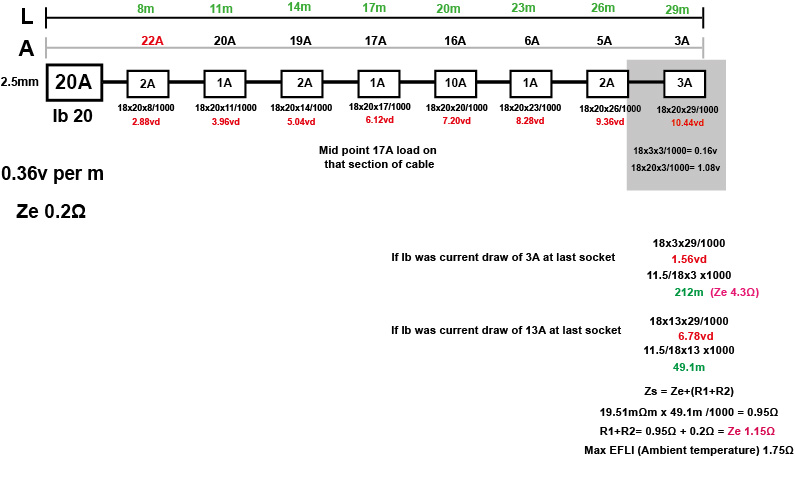
The maximum VD on any circuit will obviously be seen at the furthest socket on the circuit. The VD at any socket will be equal to the sum of the VDs in all the bits of cable (between sockets) in the path from the particular socket back to the CU.
There is no relationship between VD and the total load on a circuit, since it depends where the loads are applied. For example, if, with a 20A circuit, a load of 19A were applied to a socket very close to the CU, the VD to that socket would be very small, and therefore so would the VD be pretty low from the socket at the very end of the circuit if one applied a 1A load to it (since, even with a long cable run, the 1A flowing through it wouldn't add very much to the VD present at the socket with the 19A load), even though the 'total load on the circuit' was 20A.
For easy arithmetic, consider a 10m radial with a total load of 20A, with one socket at 1m, with a 19A load, and one socket at the end of the circuit (10m), with a 1A load. Using your 18 mV/A/m figure, the VD at the first socket (VD in the cable from CU to first socket) would be 18 x 19 x 1 = 342 mV = 0.342 V. The 9m of cable carrying 1A between first and final socket would itself have a VD of 18 x 1 x 9 = 162 mV = 0.162V. The total VD seen at the end socket would therefore be the sum of the VDs in the two segments of cable, i.e. 0.342 V + 0.162 V = 0.504 V.
Now swap the loads. With just a 1A load at 1m, the VD in the first segment of cable (from CU to socket) would be 18 x 1 x 1 mV = 0.018 V. The VD in the segment of cables between sockets (with the 19A load at the far one) would be 18 x 19 x 9 = 3078 mV = 3.078 V. The total VD seen at the far socket will therefore be 0.018 + 3.078 = 3.096 V, about 6 times the VD in the first case (both cases being for a 20A total load).
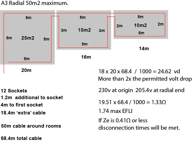
Unlike what eric seems to have found for ring finals, I'm not even aware of any 'rule of thumb' guidelines about the distribution of loads on a radial circuit. However, if one were to extrapolate pro-rate from eric's figure, one would assume (I think pretty 'pessimistically') that a "20A radial" had a 12.5A load at the furthest point, and the remaining 7.5 distributed evenly along the length of the circuit. That would equate mathematically to an 'average load' over the full length of the circuit of 16.25 A (12.5 + {7.5/2}) - so, to get a VD of 11.5V (5% of 230 V) with 18 mV/A/m, one could have a cable length of about 39.3 metres.
Does that help at all?
Kind Regards, John