DIY new lighting circuit

Joined
7 Feb 2012
Messages
54
Reaction score
0
Location
Selkirkshire
Country
United Kingdom
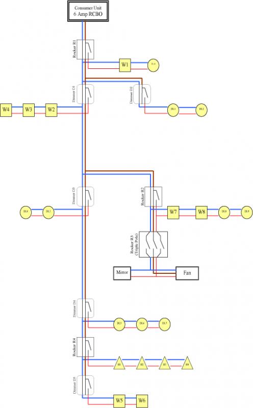
Haven't done lighting before but this is the plan. It is being inspected by Building Control though. The lights I'm using are some wall lights (the 'W' on the diagram), and downlighters.

The wall lights don't have space for a common so I've had to run that from switch to switch. Wall lights will probably just have normal 60W bulbs in as I need to be able to dim them.

I'll be using Aurora Sola downlights with LED bulbs, so no transformers and can be covered directly with insulation. The triangular 'H' are a few halogens underneath kitchen units. Will be using bathroom-rated lights in the appropriate areas.

The 'mirror' thing is a demister, that I want to operate with the fan. What I want to do is mount the triple-pole fan isolator right next to the lightswitch for the bathroom, which effectively gives you manual control over the fan like I want. But will Building Control object?

I was going to cable it in 2.5sqmm T&E, slightly overkill perhaps but I've got some left anyway.

Sorry the diagram hasn't come out as big as I'd hoped. But the switches with square edges are one-way rockers, and those with rounded edges are one-way dimmers. Brown common live, red switched live and blue neutral.


Can anyone see any problems?

Thanks.

View media item 43122
 
Sponsored Links
Oh Dear!
Forget 2.5mm T&E you will struggle to fit the conductors in the terminals.
Is this one lighting circuit for the whole house?
The diagram is wrong as it appears to show you are wiring in series rather than parallel. For example Dimmer one shows a switch live and neutral going to W2 - with a permanent live, switch live and neutral through W3 and W4. Whereas if you run switch live and neutral to W2 you should just run switch live and neutral from W2 to W3 and then onto W4. The permanent live and neutral should go straight to the next switch - if you are providing the power through the switches as you state.
Where are your calculations? You know maximum demand, cable sizes, MCB sizes etc.
Where is your cpc - or exclusion note.
You need to ask the building control inspector as what they will accept or not - they are the ones who are making that decision not us.
Auro downlights require specific insulation and even then it must laid according to their instructions - I wouldn't trust downlighters anywhere near insulation.
Does the demister have a transformer and does the fan have a timer? The link to the fan may depend on the manufacturers instructions.
 
The diagram is wrong as it appears to show you are wiring in series rather than parallel. For example Dimmer one shows a switch live and neutral going to W2 - with a permanent live, switch live and neutral through W3 and W4. Whereas if you run switch live and neutral to W2 you should just run switch live and neutral from W2 to W3 and then onto W4. The permanent live and neutral should go straight to the next switch - if you are providing the power through the switches as you state.
Although it's a bit confusing, and somewhat inconsistent with the OPs statement about running 'common' from switch to switch, my assumption from the diagram was that the permanent live was simply passing through W3 & W4 (to get to the next switches) - in which case I don't think there's anything conceptually wrong with the general idea of the proposed arrangement, is there?

Kind Regards, John.
 
Although it's a bit confusing, and somewhat inconsistent with the OPs statement about running 'common' from switch to switch, my assumption from the diagram was that the permanent live was simply passing through W3 & W4 (to get to the next switches) - in which case I don't think there's anything conceptually wrong with the general idea of the proposed arrangement, is there?
Kind Regards, John.
You're kidding aren't you! You're talking a load of rubbish - or are you just trying to wind me up.
The diagram is the wiring plan - the wiring plan is wrong. If its confusing its wrong. Why should a diyer's plans be set to a lower standard than the professionals.
Remember that the plan should accompany the Electrical Installation Certificate and a copy together with the circuit calculations should be left next to the consumer unit.
Following that plan the OP is going to run his permanent live, neutral and cpc as well as his switch live in and out of his wall lights!!! Having already told us there is no space in the wall lights.
The radial circuit should be shown separately in an out of the switches - the switch live, neutral and cpc should also be shown separately leaving the switch and linking from lamp to lamp.
 
Sponsored Links
You're kidding aren't you! You're talking a load of rubbish - or are you just trying to wind me up.
Not rubbish, IMO, and definitely not an attempt to wind anyone up.

The diagram is the wiring plan - the wiring plan is wrong. If its confusing its wrong. Why should a diyer's plans be set to a lower standard than the professionals.
I'm not disagreeing with that. What I said is that, if my interpretation is correct, "I don't think there's anything conceptually wrong with the general idea of the proposed arrangement". As you say, the diagram, as it is, is clearly not satisfactory to accompany an EIC etc. However, I thought the OP wanted comments on the proposed wiring arrangement, not the diagram.

Following that plan the OP is going to run his permanent live, neutral and cpc as well as his switch live in and out of his wall lights!!! Having already told us there is no space in the wall lights.
That's the most confusing bit, and the reason we need clarification as to whether my interpretation is correct.

The other confusing bit was your reference to "wiring in series rather than in parallel". What on earth did you mean by that?

Kind Regards, John.
 
Sorry, this was an old design, I tried to upload the new design, where the common does not run through the lights but only the switches, but it seems to have gone back to the old one.

Here is the image I meant to upload:

Sorry for the confusion.
 
Okay if you are going to do this drawing properly you need to show that the neutral loop in the switch is actually into and out of a terminal block located inside the switch.
You also need to be more clearer about the fact that both live, neutral and cpc loops are occurring inside the switch - on a couple of occasions you show the brown and blue cables terminating (in a junction box one could assume?) outside the switches.

The other thing is that the fan and probably the mirror manufacturers instructions will require you to fuse down the fan and mirror via an 3Amp FCU which you do not show and unless the fan has a timer you don't need three core and earth.

By the way, according to their website, there are no Aurora LED lighting downlight units that can be covered in insulation. The two that I saw required 100mm gap all around. Also LED lights do require either constant current or constant voltage transformers that are either incorporated into the lamp unit itself or form part of the lighting unit as in the case of the two on the Aurora website.
You still need to show the demand calculations that lead you to determine the size of the cable and MCB. What you are doing with the cpc? And as I said don't bother with 2.5mm2 you will just get frustrated trying to fit the conductors in the terminals.
I have no noticed from the various posts you have made that on most occasions you choose only to answer the questions you want to rather than some of the more important ones. Bit like the ones I have re-asked above. Ignoring the issues in the hope that they go away is not the way to learn.
 
Ta for that, sorry I got the drawing wrong.

Yes, it's not a great drawing in terms of showing exactly how things will terminate.

Yes, the fan probably does need a 3A fuse; I'll have to think about how to get one in. Guess I could just put an unswitched one somewhere accessible up in the void? Fan does have a timer so needs triple-pole isolator.

The downlights I was looking at were:
http://www.downlightsdirect.co.uk/insulation-coverable-downlights.html

I wasn't aware of any more restrictions but I'll perhaps give their tech support line a ring on Monday. Any ideas in the meantime?

I haven't done any demand calculations, but because I'm going for LED downlighters they'll use virtually no juice. And there will be six wall lights, which might have a 60W bulb in each, but I can't see how that wouldn't be ok with a 6A RCBO and 2.5sqmm cable. I hear what you're saying about fitting the terminals, but I've got quite a bit left so I'm tempted to try, I don't mind a day of fiddling.

As for cpc - that's earth isn't it? All my light fixings have earth terminals so was just going to make sure the earth is attached to everything - metal boxes of switches and light fixings.

This circuit is for most of the flat, but there will be one other circuit which I'm not doing yet.

Thanks.
 
I hear what you're saying about fitting the terminals, but I've got quite a bit left so I'm tempted to try, I don't mind a day of fiddling.

If you want to save your self a day of fiddling, then a big headache, then a visit to your suppliers for a roll of 1 or 1.5mm, then another day of re-wiring, then a day of less frustrating fiddling, might i suggest you cut to the chase and get a more sensible size of cable to start with.
 

DIYnot Local

Staff member

If you need to find a tradesperson to get your job done, please try our local search below, or if you are doing it yourself you can find suppliers local to you.

Select the supplier or trade you require, enter your location to begin your search.


Are you a trade or supplier? You can create your listing free at DIYnot Local

 
Sponsored Links
Back
Top