

Hi
After we had a burglary I decided to review our security and thought that our perimeter could do with making more secure.
So after fitting a selection of external lights and PIR triggers and then cameras I have now looked at the panelled UPVC back door.
I replaced the bottom back panel several years ago with a 28mm (reinforced with ply but still seems not ideal) panel bought from ebay. The back-door is situated in a secluded area and it is not prone to any external vibrations from traffic etc. So I thought that I would replace the magnetic door contact with one of these...
http://www.safetechsuppliers.co.uk/...cktec-digital-shock-sensor-white-grade-3.html
a Shocktec digital shock detector with magnetic contact.
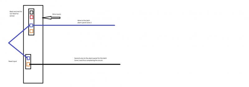
Piccie of internals....
Would I be right in thinking that the magnetic door contact's wiring would go to the Alarm connectors and then the 12v to where it is marked and finally a 12v+ to the LED (which I could take from the 12v + I am feeding the unit..?)...? The tamper I am not bothered with.
In the area we live there have been a number of burglaries over the last few weeks and a neighbour was broken into when they broke through the back door by damaging the bottom panel. Even though the kitchen is protected by a PIR I would sooner detect them on trying to get in rather than when they are in.
The manual for it is here...
http://download.homesecuritystore.com/downloadmanual.aspx?FileName=RK600S00000A_Install.pdf
My old magnetic door contact has been wired (by me) with std 6 core alarm cable and it is fitted to a Optima XM6 Alarm Box. My back door is wired to Zone 2. The manual for the alarm I have uploaded to my Dropbox account...
https://dl.dropbox.com/u/81974590/optima.pdf
albeit mine has six zones and not four as shown in the above manual.
Realising that my old magnetic contact did not require a 12v supply I would like to ask for a little guidance please before I decide to try and fit this myself. Could I take the supply (works between 12v and 16v) from the 13v output terminals shown in the Optima manual...?
I have noticed that zone 2 is also considered a timed / walk zone. This I do not need and it is stated that it can be used as an immediate zone but I do not know how to change that without compromising also zone 1's walk in feature, which is very much needed for the front door entry. Unless it means that zone 2's timed feature would need zone 1 to be triggered first and if it isn't then it will work as an immediate zone..?
EDIT: Just checked and indeed Zone 2 is an immediate one (so that is fine) if Zone 1 has not been triggered first.
Thanks for any advice and sorry for the first post being rather large")
After we had a burglary I decided to review our security and thought that our perimeter could do with making more secure.
So after fitting a selection of external lights and PIR triggers and then cameras I have now looked at the panelled UPVC back door.
I replaced the bottom back panel several years ago with a 28mm (reinforced with ply but still seems not ideal) panel bought from ebay. The back-door is situated in a secluded area and it is not prone to any external vibrations from traffic etc. So I thought that I would replace the magnetic door contact with one of these...
http://www.safetechsuppliers.co.uk/...cktec-digital-shock-sensor-white-grade-3.html
a Shocktec digital shock detector with magnetic contact.
Piccie of internals....

Would I be right in thinking that the magnetic door contact's wiring would go to the Alarm connectors and then the 12v to where it is marked and finally a 12v+ to the LED (which I could take from the 12v + I am feeding the unit..?)...? The tamper I am not bothered with.
In the area we live there have been a number of burglaries over the last few weeks and a neighbour was broken into when they broke through the back door by damaging the bottom panel. Even though the kitchen is protected by a PIR I would sooner detect them on trying to get in rather than when they are in.
The manual for it is here...
http://download.homesecuritystore.com/downloadmanual.aspx?FileName=RK600S00000A_Install.pdf
My old magnetic door contact has been wired (by me) with std 6 core alarm cable and it is fitted to a Optima XM6 Alarm Box. My back door is wired to Zone 2. The manual for the alarm I have uploaded to my Dropbox account...
https://dl.dropbox.com/u/81974590/optima.pdf
albeit mine has six zones and not four as shown in the above manual.
Realising that my old magnetic contact did not require a 12v supply I would like to ask for a little guidance please before I decide to try and fit this myself. Could I take the supply (works between 12v and 16v) from the 13v output terminals shown in the Optima manual...?
I have noticed that zone 2 is also considered a timed / walk zone. This I do not need and it is stated that it can be used as an immediate zone but I do not know how to change that without compromising also zone 1's walk in feature, which is very much needed for the front door entry. Unless it means that zone 2's timed feature would need zone 1 to be triggered first and if it isn't then it will work as an immediate zone..?
EDIT: Just checked and indeed Zone 2 is an immediate one (so that is fine) if Zone 1 has not been triggered first.
Thanks for any advice and sorry for the first post being rather large
 )
)