After seeing the answer given by the manufactures. I started to wonder what the limits were? So I started to wade through the 17th Edition to try to find some answers.
What is a “Long period”? considering the use of RCD protection the ELI is no longer such a consideration but of course we are still concerned with Live cable overload so I have been looking at BS7671:2008 so see how quickly at MCB has to trip for Live overload faults. 433.1.5 seems to be start of time reference but 434.5.2 is where the time seems to be specified.
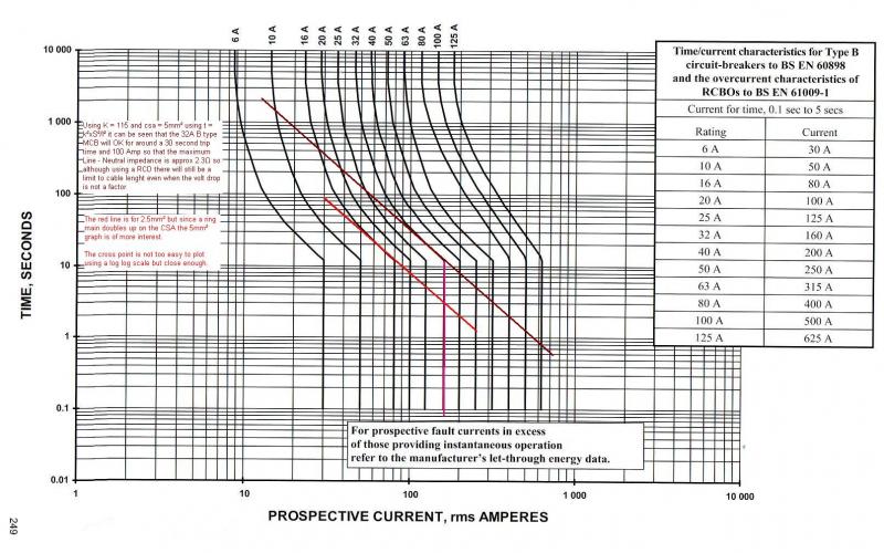
Looking at a ring main with a fault at mid point at 160 amp and above it will trip in 0.1 seconds so only interested in valves of overload between 32 and 160 which will need to trip between 3 and 90 seconds.
Using 5mm² with K at 115 a graph was draw and so it could be superimposed on the graph given in fig 3.4 a log log scale was used. Which produced a straight line. At first I entered 2.5mm² as cable size then realised for a ring main 5mm² would be CSA.
The results were a surprise as I had expected to see a cross over point. But it was nearly the same angle and position as the 32A MCB plot followed. As a result it is very hard to arrive at an accurate point at which the two lines cross.
However it does show that the limit will be somewhere around a 100A PFC limit or an impedance of around 2.3Ω which would exceed the permitted volt drop by a huge margin.
So with a RCD it would seem volt drop is the limiting factor.
The forms for the 17th Edition state: “12 Earth fault loop impedance Zs This may be determined either by direct measurement at the furthest point of a live circuit or by adding (R1 + R2) of column 6 to Ze. Ze is determined by measurement at the origin of the installation or preferably the value declared by the supply company used. Zs = Ze + (R1 + R2). Zs should be less than the values given in Appendix 2 of the On-Site Guide or Appx 2 of GN3.” Maybe some kind sole will tell us what those values are as my copies are out of date.
Although the Forms are supposed to be for the 17th Edition it still refers to EEBADS not PEBADS so it may not be correct in other areas.
As with Line instead of Live I am sure I and many others forget and enter EEBADS on forms instead of PEBADS? Does it really matter?
Of course with different values for K will alter results and with K = 100 there is a problem where the magnetic part of the trip is only part within spec but in real terms I am sure the small amount it misses by would not really cause any problems there must be some lee way.
But the idea that with RCD protection you can go as long as one likes is plainly not true.


 - and as sub main to a distribution board in a theatre isn't going to be a good idea to put it on one.