Hive 2 on Vaillant EcoTec Plus 831

Joined
26 Mar 2016
Messages
3
Reaction score
1
Country
United Kingdom
Hi all, apologies, I know all the experts probably get tired of coming to the aid of DIYers. Having a grand total of two wires to move, I didn't expect there to be much of an issue installing. I would appreciate any assistance in getting my Hive to a point where it actually turns on the boiler.

I was replacing a VRT392f which is wired externally to the boiler and cabled in to the eBUS terminals. The RT 230v and RT 24v terminals were linked. As per the manual, the polarity for the eBUS connection is irrelevant. All works fine with this setup.

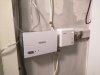
So, I plug in the hub and set about sorting the receiver.

After isolating everything...

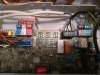
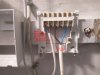
I removed the link (loop) on the RT 230V connector. I remove the connections from the eBUS terminals inside the boiler and connect them to the RT 230V connectors.

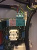
At the other end, I connect to terminals 1 and 3 on the Hive backplate. There is no obvious indication of polarity for these connections at the boiler side (see attached images)

I provide a fused 3A spur to the Hive receiver from the same power that is providing the boiler. I have not looped from the boiler to the Hive receiver since the terminals are far too small.

I close all cases etc. and fire up the boiler. It promptly comes on and stays on constant.

A quick read of the manual (page 30) states "If you connect a 230V AC time and temperature control to the boiler, then remove the bridge at input 24V = RT."

I re-open the boiler, remove the bridge, close it up and start the boiler and receiver back up again.

The boiler boots and stays off this time. I manually call for heat, I hear the relay switch and, the boiler does nothing.

There are no fault codes showing on the LCD display and as far as I can tell, the receiver has no effect on the boiler's operation.

I've attached images below showing the wiring - which obviously isn't "hard" - so why doesn't the receiver activate the boiler when it calls for heat (green light is on and the relay clicks)? Is it related to the previous use of a VRT392f that I now need to tell the boiler to not use the eBUS? Does the eBUS need a loop now instead?

Any help would be greatly appreciated.

Thanks
 

Attachments

  • internal_wiring.jpg
    internal_wiring.jpg
    249.4 KB · Views: 9,285
  • hive_backplate.jpg
    hive_backplate.jpg
    169.4 KB · Views: 4,743
Sponsored Links
I've attached images below showing the wiring - which obviously isn't "hard"
Yet you've managed to get it wrong...
You've connected your blue wire into an unused terminal in the boiler.
There is no need for a second fused spur.
One of the gas engineers will be along shortly to bo***ck you for removing the boiler casing.
The cables need fixing to the wall to take the strain off of the terminals.
The blue switch wire needs to be correctly identified with brown sleeving.
As this is a fixed wiring point an earth should have been provided, even though the current Hive does not use it.
A 4 core flex connected straight into the boiler would have been the correct way to wire this.
If both switch fuses need to be switched off to cut all the power to the heating system, a clear and durable warning label must be fixed to the boiler to warn anyone working on the system of the danger.
You need to put 230V onto the RT terminal when you want the boiler to fire, you are currently switching nothing to the RT terminal which is why nothing is happening.
 
Thanks Echo, I don't disagree that I had got it wrong, hence why I returned everything to its as was state and posted my question. It isn't hard, it is just made harder by incomplete instructions - there's no suggestion that it's an unused terminal in the boiler instructions and yes, had I known this, it would have been obvious that I was switching nothing to RT.

I should clarify, it isn't a second fused spur, it's the same fused spur providing power to the boiler, one switch, both the receiver and boiler go off.

They can ******* me if they want, there's a service appointment in 8 days. If I die of CO poisoning before then, I'm sure my ability to replace the front of a boiler lined with foam, clip two steel clips and replace a 10mm bolt can be called in to question. I shall monitor the engineer during his visit to see what magic he does differently to me that only GSEs can do.

The cable from the boiler is fixed to the wall out of the photo. The Hive receiver acts as a strain relief when closed but I should add that I would have used additional fixings on the smaller cable had I got everything working.
Agreed about the switched live, again, this would have been done during the finishing off phase - had I managed to get it working. I'm sure you're sitting there thinking I'm yet another cowboy clueless DIYer, I'm not, I'm just not a Vaillant trained engineer. I should add that I've read numerous other posts from GSEs around the internet struggling with wiring in wireless thermostats to this very boiler, so I'm not alone.

The Hive receiver is double-insulated and makes specific reference to that in the instructions. Why they would say this and then still expect you to provide an earth is surely a potential legal hazard and largely dangerous. If you truly believe it is necessary, I'll provide an appropriate earth.

I took the following link and attempted to apply the same logic (terminals 3 and 4) to the RT 230v block in my boiler - it being the same model. As it is, Vaillant changed their internal wiring and layout between the two ages of the boilers so I was left with having a go. http://www.alswebpage.net/hive-with-installation-with-a-vaillant-ecotec-plus-824/

The sparky that originally installed the boiler used two three-core cables. One for power in to the boiler with an earth, the other for eBUS connectivity from the boiler to the externally located RF controller - using only two cores. I see no reason why I can't use the old eBUS flex for the switched live to the Hive Receiver (L on boiler to 1 on Hive Receiver) and back to RT (3 on Hive Receiver to RT 230v on boiler) but provide a separate perm live and neutral to the Hive Receiver from the same fused spur as provides the boiler. I'm simply avoiding putting three cables in to a tiny terminal block (L) on the boiler.

Can I confirm then:
At the boiler side: I should move the brown cable currently going in to RT 230v to the live terminal of the boiler.
At the boiler side: I should move the blue cable to RT 230v and sheeth it appropriately.

At the Hive side: Sheeth the blue cable.
At the Hive side: Add additional strain relief fixings.


Thanks again.
 
Can I confirm then:
At the boiler side: I should move the brown cable currently going in to RT 230v to the live terminal of the boiler.
At the boiler side: I should move the blue cable to RT 230v and sheeth it appropriately.

At the Hive side: Sheeth the blue cable.
At the Hive side: Add additional strain relief fixings.
Yes,
Yes,
Yes,
Yes.
 
Sponsored Links
Thank you for your assistance. Cables moved and sheethed. Strain relief added (piccy). Job done and all is working now.

I also noticed some stray wire strands left from the original installer inside the wiring/pcb section which I hoovered up - couldn't have been me, I didn't cut anything.

Again, thankyou very much.
 

Attachments

  • strained.jpg
    strained.jpg
    141 KB · Views: 1,742
Thank you for your assistance. Cables moved and sheethed. Strain relief added (piccy). Job done and all is working now.

I also noticed some stray wire strands left from the original installer inside the wiring/pcb section which I hoovered up - couldn't have been me, I didn't cut anything.

Again, thankyou very much.
Can you confirm is this right ???image.jpg
 
Thank you for your assistance. Cables moved and sheethed. Strain relief added (piccy). Job done and all is working now.

I also noticed some stray wire strands left from the original installer inside the wiring/pcb section which I hoovered up - couldn't have been me, I didn't cut anything.

Again, thankyou very much.
Can you confirm is this right ???View attachment 97023

Correct.
It's a hive I have and a Vaillant ecotec 837 plus ...... Should be just the same yeah ?
The 230v RT on my boiler does not have a plug in it so I can attach my wires, any ideas ?? Can I buy one ??
 

Attachments

  • image.jpg
    image.jpg
    88.5 KB · Views: 2,842
Can you confirm is this right ???View attachment 97023

Did exactly as this drawing from Bomberbaz and worked perfectly. wired in the earth as well to the hive receiver.
Was quite tricky getting 3 wires in to the Live, managed to get it done.

Connection for the receiver to the hub took a few turns but got there in the end. Was flashing red on the hub, but just reset the wires in to the router and turn the power off to it for around 5 mins and try again.
 
Here is how is how i wired the Hive single channel receiver to a Vaillant ecotec 825 combi boiler,
The L/N/E from the fused spur will already be wired in at the X1 terminal to power the boiler

wiring instructions for the hive receiver to the boiler
I used a 5 core cable bought from Screwfix

– Hive Receiver to Boiler at X1
L to L (brown)
N to N (blue)
1 to L (black)
3 to RT 230v (grey)
E thether to E (green/yellow)

Took a while to get 3 wires in to the Live connection at x1, so take your time on it.

Important**
Remove the looped wire at the RT 24V (x100)

Also a similar thread on this post
//www.diynot.com/diy/threads/hive-2-on-vaillant-ecotec-plus-831.456243/

then just follow the steps to connect the thermostat and internet controls

Thanks

Read more: //www.diynot.com/diy/threads/hive-and-vaillant-832.455984/#ixzz4SRhAZehl
 

DIYnot Local

Staff member

If you need to find a tradesperson to get your job done, please try our local search below, or if you are doing it yourself you can find suppliers local to you.

Select the supplier or trade you require, enter your location to begin your search.


Are you a trade or supplier? You can create your listing free at DIYnot Local

 
Sponsored Links
Back
Top