Yes, what Bernard recommended there are buffer chips to go between the logic and the relays. That's one of the ways of dealing with back EMF, but as John said, that's be a problem whatever the voltage of the relay coils.

You are using an out of date browser. It may not display this or other websites correctly.
You should upgrade or use an alternative browser.
You should upgrade or use an alternative browser.
Home Automation - High Voltage side
- Thread starter dunny
- Start date
Are you talking about the reference in that thread to 'back EMF'? If so, that's an issue which has to be addressed with any relay driven by semiconductor circuity, no matter what coil voltage (5V, 12V or whatever).
Kind Regards, John
That is the post I am referring to.
Specifically the bits below but having re-read I think he is just saying just make sure that the circuitry is protected from back EMF of the relays regardless of what they are.
Don't drive direct from 5 volt logic. Use the 5 volt logic to drive buffer chips that can switch 12 or 24 volt relays. ULN2803 or similar will give you 8 channels with a 2.7 KΩ load on the logic devices.
http://elcodis.com/parts/6011583/ULN2801_p2.html#datasheet
This provides protection of the logic devices from the back EMF of the relays when they are switched OFF. Fit the ULN2803 in sockets so they can be replaced if damaged by a relay.
D
Yes, I think that's all it's saying. They're talking about using buffer chipsto provide the protection but, as has been said, you could just as well use a transistor (with a 'reverse' diode across the relay coil to protect the transistor from back EMF).Specifically the bits below but having re-read I think he is just saying just make sure that the circuitry is protected from back EMF of the relays regardless of what they are.
Kind Regards, John
Yes, I think that's all it's saying. They're talking about using buffer chipsto provide the protection but, as has been said, you could just as well use a transistor (with a 'reverse' diode across the relay coil to protect the transistor from back EMF).
Kind Regards, John
The PCB has optocouplers for isolation so this should be OK. I went around the houses a bit but I think I can actually use the standard 5v relays rated at 230v/10A.
D
Yes, but the 'optocouplers' will provide isolation, but will not protect the driver circuitry (transistors or whatever) from back EMFs. However, if you're using a ready-made 'relay board, it will probably have the required protection built in.The PCB has optocouplers for isolation so this should be OK. I went around the houses a bit but I think I can actually use the standard 5v relays rated at 230v/10A.
Kind Regards, John
Great - that's all you need, then.Yes, the board has a transistor and a diode across the relay.
Kind Regards, John
- Joined
- 27 Jan 2008
- Messages
- 29,120
- Reaction score
- 3,567
- Location
- Llanfair Caereinion, Nr Welshpool
- Country

There is a balance between price and ease of construction. Using a PIC and optical isolators you can make it very cheap, however I found programming PIC's hard, however use a PLC and programming is far easier but the cost is higher. So step one is to decide what level is your programming skills?
With the PLC you have no volt contacts already and you can also get plug in modules for the Arduino and there is also the Raspberry pi although never tried using the latter. Some of the Siemens LOGO I am told are easy to program, although I have never used one. I used the older generation of PLC.
My son is telling me no point in learning how to use a Arduino now the ready built units have dropped price.
But the big problem with home automation is the requirement to use type tested equipment where there is an ordinary person in control. I could build a wonderful automated system, but then I could not rent the house, and its value would drop as it would all need ripping out before it was sold. So with relays fitted in a consumer unit all may be A1, but the same relays fitted in an adaptable box on DIN rail may not be accepted. So the way around the problem is not to make the Automation fixed, but have it so it can be easy removed.
When I was younger I did loads to my house. Today from time to time I find these attempts, but I can't remember what I did and why I did it, some was done 25 years ago.
Even very well controlled systems can go wrong. Mother had a stair lift fitted, the design faults have to be seen to be believed, such a basic error like if battery voltage drops, it stops, not much good when you have a disabled person on the lift, should be a warning first before the battery gets that discharged, load of sensors on the chair, but non on the leg which needs putting down first and can't be seen from the control point. If some one is injured then the installer would be liable and they would in turn point the finger at the designer.
The problem with home automation is if the same errors are made, you would be liable, and you would not have the insurance. With accidents it is most likely to involve a visitor who does not really know how it all works.
So with relays fitted in a consumer unit all may be A1, but the same relays fitted in an adaptable box on DIN rail may not be accepted.
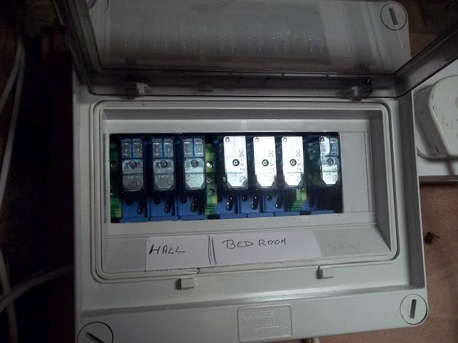
Finder ( or equivalent ) relays on the DIN rail base fit snugly into consumer units.
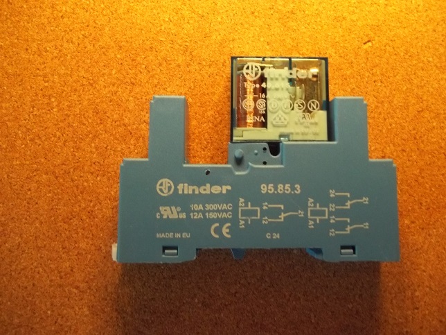
Indicators can also be plugged into to the bases if required to show the state of the relay
Provided the cabling is well thought out the mains cables can be left in place with only the "intelligent" unit being removed and cables from the switches on walls then connected directly to the corresponding relay. Then the only "abnormal" item would be the 12 volt DC power supply for the switches and relay coils.,and its value would drop as it would all need ripping out before it was sold.
Using assembly language is "inconvenient" but using a high level lanuage requires the hardware to match the language and this imposes restrictions on what can be done and can waste a lot of resource in the processor.however I found programming PIC's hard,
There is a balance between price and ease of construction. Using a PIC and optical isolators you can make it very cheap, however I found programming PIC's hard, however use a PLC and programming is far easier but the cost is higher. So step one is to decide what level is your programming skills?
My programming skills are pretty good, it's been a while but I work in the software industry and started my career as a technical consultant. I prefer higher level OO languages and the likes of the Arduino, ESP8266 work well with this. Don't think I fancy low level assembler though!!
So the way around the problem is not to make the Automation fixed, but have it so it can be easy removed.
My thoughts on this are that everything that is to be controlled (which isn't every outlet) would be wired back to the board in a star configuration. If I then wanted to remove the automation it would just be a case of adding the cable back directly to the CB? With the lights, and other things that need a wall control switch (e.g. blinds) I think there are a couple of choices. Place relays near the switch and interrupt the supply there (don't fancy this) or put in redundant cabling that can be connected back up in a traditional manner easily enough. For this option I would probably go for a cable that terminates in (or next to) the automated switch plate and if it needed removing then it would be a case of replacing it with a switch. I appreciate this would mean more cabling but this would futureproof the install.
Would it be possible to do the latter and leave the wire connected under the floor and terminating in an insulated connector next to the automated switch plate?
Thanks
D
DIYnot Local
Staff member
If you need to find a tradesperson to get your job done, please try our local search below, or if you are doing it yourself you can find suppliers local to you.
Select the supplier or trade you require, enter your location to begin your search.
Please select a service and enter a location to continue...
Are you a trade or supplier? You can create your listing free at DIYnot Local
Similar threads
- Replies
- 12
- Views
- 8K
- Replies
- 10
- Views
- 7K