Honeywell Flex 50 panel upgrade

Joined
17 Feb 2020
Messages
32
Reaction score
1
Country
United Kingdom
Hi all,
I have bought a Honeywell Flex050 panel, to replace my old Galaxy 16+ panel, following advice to upgrade from GalaxyGuy several months ago. I am now looking foward to installing it instead of having festive fun (boo hoo).

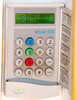
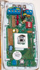
My first question is whether the new panel will be compatible with the two existing keypads (which are marked 'Model 605', and I assume were installed 20 or so years ago, at the same time as the panel), and/or if anybody can recommend replacements for the keypads that do not cost the earth? I am looking just for keypad functionalty, not fob / promximity detectors.

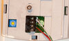
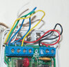
Apart from the repalcement panel, I intend to replace the bellbox, but leave the wiring and PIRs as is, for the time beiing at least.

Any advice would be gratefully received..

Thanks,
Jon
 
Sponsored Links
I'm not even sure what a model 605 keypad is. It will probably work with the Flex, as the protocol hasn't changed. You'll be able to pick up used non pros CP037 keypads cheap enough. PM me, as I have new CP037's.

I would advise fitting resistors to your current detectors, keeping everything as double balanced zones. If you need help with that, just post a picture of the inside of your sensor and we can mark it up with resistor positions / wiring.

I use the Texecom dual piezo backlit bell boxes, they're nice and loud and look decent too.

New panels should have 3.51 firmware. If not new, it's best to fit 1k resistors across the zones, fit a link across aux tamper and 0v, tape down the lid tamper, connect 12V battery and test the board for at least 24hrs prior to installing.
 
Thanks for the reply and advice.
Attached are pics of the Model 605 keypad, and its rear connections, also the PIR innards and nameplate.

You advise adding resistors, presumably one to each PIR. Please can you specify where / how to add, and what value resistor I should use?

My new bellbox is a texecom Odyssey X.

The Flex panel was bought on ebay, unused. It has come in a sealed box with manuals etc. on a CD Rom and a bag of 3k ohm resistors. There is no mention of the installed firmware version anywhere that I can find. I presume I can only determine the version once it is powered up and fitted to a keypad.

Once the basic system is up and running, I'd like to make a few modifications:
1. is to add (if such can still be opbtained) a module that can dial out to my mobile phone to alert me of an activation,
2. is to add a module which can accept extension of the system via wireless devices such as PIRs, contact switches and panic buttons.
3. (if 2 is not possible) is to extend the current system by looping a new PIR onto an existing one in daisychain fashion, to avoid the disruption to decor of running a new cable. My intention is to have activation of the alarm on detection of movement by either PIR. Is this advisable / feasible, and could you suggest wiring configuration?
 

Attachments

  • Keypad.jpg
    Keypad.jpg
    457.5 KB · Views: 239
  • PIR details.jpg
    PIR details.jpg
    315.6 KB · Views: 204
  • PIR innards.jpg
    PIR innards.jpg
    407.6 KB · Views: 249
  • Rear of keypad.jpg
    Rear of keypad.jpg
    309.9 KB · Views: 196
It looks like your system is already configured for double balanced circuits. I see the resistors at the top of the sensors. So you should be ready to go. The only way of knowing if the keypads will work is to try them connected and then boot the panel.

There are two module options. Ethernet module and GSM module. If your panel is metal cased, then the GSM module will not mount in it, as it's designed for the plastic case Flex. If you use the A083-00-02 or A083-00-10 Ethernet module, you can configure the GX app to send basic push notifications for free. You can also opt for the low cost SelfMon platform (disclosure - SelfMon is my business), enabling SMS, Voice, Email, Push notifications and path monitoring.

The C079 V3.00 RF portal module can be added for wireless capability. If the metal Flex case, this needs to be in a plastic enclousure mounted outside the panel.

The Flex firmware version is always on a label on the PCB. If an FX50 metal case, it's likely to be the ADT variant.

Each sensor only requires one signal wire and 0v and +12v. So, if you have a 6 core cable, you can configure 4 separate sensors on separate zones from that cable if you extend it. There is also the possibility to add an unpowered RIO at the end of a cable, then have 8 separate sensors from that RIO. The RIO would be in a cupboard or access space, as it's unsightly to have showing in a room. On my own system there is a powered RIO in the garage and unpowered RIO's in the upper and lower attic spaces connecting multiple zones local to those areas.
 
Sponsored Links
That's great, thank you.

The firmware is indeed marked on the board (3.39). I know you said it should be 3.51 - so I'm wondering will the board work OK as is, or do I need to find a way to upgrade?

Thanks for the advice on the wiring of the sensor and how to use the spare strands. Inside the PIR that I've looked in, the 12V and 0V terminals are connected, but two additional cores of the cable are connected to the sensor terminals, as shown in the photo. This differs to your note that just one wire should used per PIR, so I'm just wondering whether this is a problem..

My panel is plastic cased, so that opens the way for the upgrades. A look online shows no C079-v3.00 modules are currently available, although C076,C077s are. My assumption is that these will not be compatible with the Flex050, but I thought this was worth checking. However that's really for later- first I need to get the panel fitted and operating properly- that's plenty of a challenge for me to begin with!
 

Attachments

  • PIR-connections.jpg
    PIR-connections.jpg
    456.6 KB · Views: 172
Last edited:
Fixes from 3.39 to 3.51 are for comm's and RF, so if you don't use these features, then no update is required. However, you can easily flash update via mini USB cable.

Your wiring is fine and pretty much standard. One of the blue or yellow cores will be 0v the same as the black core Ie. going to the same copper on the panel PCB. If you need the core for something else, you can disconnect in the control panel and just link the black over in the sensor.

The c076 and c077 are not the correct part. PM me, as I have c079 v3.00 available if you need one.
 

DIYnot Local

Staff member

If you need to find a tradesperson to get your job done, please try our local search below, or if you are doing it yourself you can find suppliers local to you.

Select the supplier or trade you require, enter your location to begin your search.


Are you a trade or supplier? You can create your listing free at DIYnot Local

 
Back
Top