Installing Hive Mini Wiring help

Joined
25 Jan 2023
Messages
10
Reaction score
0
Country
United Kingdom
I have recently purchased a Hive Mini to replace the thermostat that I had previously been using for years which gave in.

I am struggling with the wiring on this.

My boiler is an Ideal Logic Heat 24 (Heating only) boiler so I have purchased the Hive mini Dual Chan.

I am struggling with the wiring on the previous installation that I am removing to replace with the new unit.

MicrosoftTeams-image.jpg

The unit above is a TimeGuard TRT036 this looks to have the wires from the boiler coming into this and then out to the Siemens rcr10/433-gb unit (Blue, Brown, Grey, Black). The timeguard unit also looks to have a feed coming into this (Or out) from elsewhere as there are 3 blues connected to the N plug within the unit my guess is 1 from the boiler 1 to Siemans unit and 1 from/to elsewhere. There is also the Red and Grey terminating to a block as well which I am not sure where these come from either (I haven't taken all wires out to examine properly) We do have an outdoor light which seems to be connected to a switch situated below both these units. Could it be that the wiring is going from the switch > Time Guard > Light which is why I am seeing additional wiring leading elsewhere?

1674686901383.png


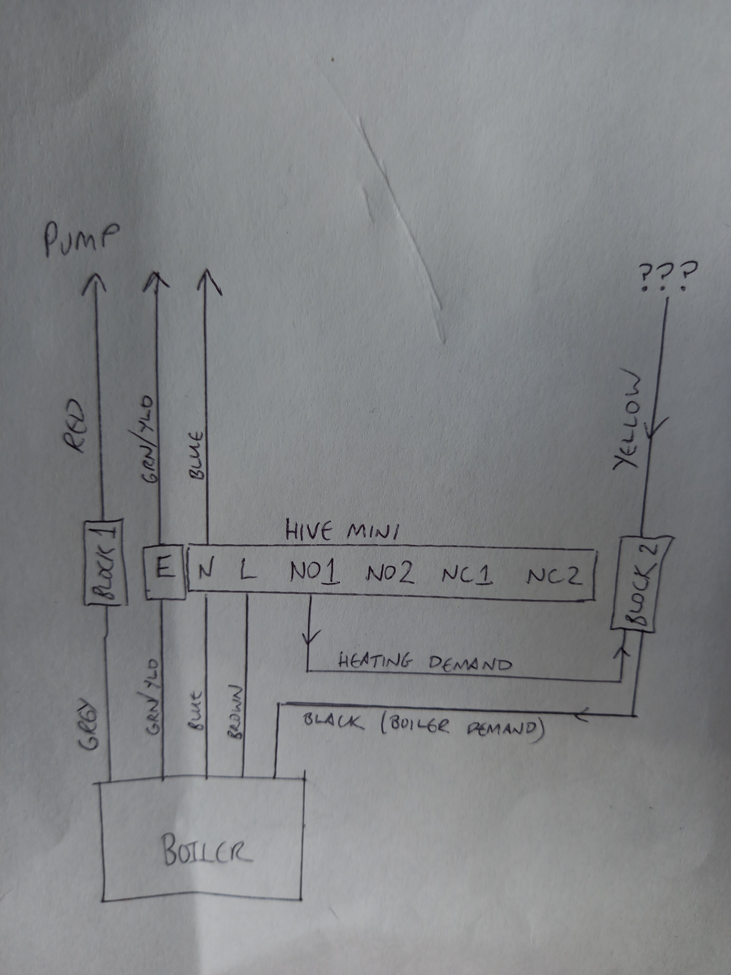
What would be the correct procedure to wire the new hive unit up? I believe I would need to remove both the units in the imaged above and have 1 feed from boiler into the Hive unit but I may be wrong about this.
 
This could be a tricky one, because the installation may have been modified and not conform to the norm. I will explain, but you may need quite a high degree of understanding with regard to electrical circuits to do this. And if you don't this maybe an installation best left to the professionals

The Hive Dual Channel Receiver usually replaces the existing programmer. This is because the heating and hot water wiring are connected there. From an electrical point of view the TimeGuard and Dual Channel Hive are identical in that they simply contain two internal switches, one for heating and one for hot water.

Therefore, the wires move from the terminals of the TimeGuard TRT036, to the terminals of the Hive receiver that have exactly the same function.

Apart from the L and N, I can't see wires connected to the other TimeGuard terminals in your photo and your text suggests you may have moved some of them already? However, if there aren't / weren't any wires connected to NO1 and NO2 then something is amiss. They are the terminals that are responsible for controlling the Central Heating (NO1) and Hot Water (NO2)

Having said that, if the Siemens thermostat you have is of the programmable type (i.e. provides both time and temperature control) then the heating channel of the programmer is not required, so, it's possible that the CH ON (NO1) connection isn't used and the wire that was in there has been moved to L to bypass the programmer. If this is the case, the Central Heating channel of the TimeGuard won't be controlling the central heating presently. [Easy to check if it does or not] If this is the case, to transfer to Hive this connection would need moving back to CH ON. If there is a connection to CH ON you can ignore this.

TimeGuard
Capture.JPG


Hive.JPG


The L and N connections are marked the same, so fairly straightforward, then,

From the above diagrams:
TimeGuard 'CH ON' would correspond with Hive 'Heating on'
TimeGuard 'HW ON' would correspond with Hive 'Hot water on'
TimeGuard 'HW OFF' would correspond with Hive 'Hot water off' (This connection may not be used)

Then the Siemens RC10 room thermostat receiver is no longer required and should be decommissioned. This is done by connecting the wires in LX and L1 together. This can be done at the receiver and the receiver left in situ, but won't do anything. Or, by tracing the cable from the receiver back to its origin. Note where the wires that go to LX and L1 originate from before disconnecting the entire cable. Then insert a link to join together the two terminals where the wires going to LX and L1 have just been removed from.

It's possible that someone has connected the outside light to the heating circuit. If when you turn off the 3A fused connection unit that supplies power to the boiler and the heating system and find the outside light no longer works, you will know. Although, it's more common for the terminals of a programmer to be used as a junction box for other heating system components.
 
Good morning,

Thank you for the response on this Stem.

I have not moved any wires as when I opened the box and saw this mess I just closed it up and thought I would seek advice.

The Time Guard doesn't control our hot water but only controls the heating or it does but never worked :LOL:. The Siemans doesnt have a time controller and has only ever been used as a connection source for our wireless receiver which was only temperature controlled.

My assumptions of the wiring are as follows

1674729433052.png


This looks to be how the earths, live and neautrals are connected. Without looking (Im in work at the moment) I expect from the boiler to the timeguard to be a connection to NO2 (Black) into the Siemans L1. The question is The LX from the siemans to the Timeguard looks to be terminated into the block with the red wire connected as well so these look to join but I am not sure where the red wire is coming from (Boiler possibly?)

Taking this into consideration could this be a possiblity this is how the wiring is done?
1674730259820.png


I believe I should be able to just remove the Timeguard and Siemans and do the following connections

Live > Live
Neutral > Neutral
E > E

TG NC2 > Hive Heating off
TG NO2 > Hive Heating On

And then connect
Light L > Hive L
Light N > Hive N
Light E > Hive E

Would this be correct to do the wiring in this way by just removing the wiring to the Siemans and then move the Time guard wiring and Light wiring into the Hive unit.
 
Sorry much of that doesn't make sense to me.

The Time Guard doesn't control our hot water
So what does then? Are you sure it's a heat only boiler with a hot water cylinder and not just a combi?

The Time Guard....only controls the heating or it does but never worked
If there aren't any wires to the TimeGuard NO1/CH ON it never will have done, so what does control the on/off times for the heating?

The thermostats usually control motorised valves, either 2 x 2-Port valves (aka S-Plan) or 1 x 3-Port valve (aka Y-Plan) they have internal switches that control the boiler, But I don't see them or a pump in your diagrams.

If there aren't any connections to NO1 and NO2 then the TimeGuard isn't actually doing anything, it's just a junction box.

Based on your photos and posts and without seeing it in person. I think the whole lot needs ripping out and wiring up again from scratch.
 
The system we have currently is controlled by the time guard. We have times set for when the central heating will currently come on and can set this to always on so that the heating will be on until turned off. This used to be controllable with our wireless thermostat.

We only get hot water to our taps when the heating is either on or been on for a while or the immersion heater has been on ti heat the water in our tank which would indicate its not a combination system that is being used.

I will agree the whole system is abit janky.

I will double check the connections that are going into the time guard when I am home later and give you an update.
 
Update for you there is a black cabe going into the NO1.

Does this make things clearer as to what need to be done?
 
Hmm....a little bit, it sounds like the TimeGuard has a connection in NO1 which should go to the Siemens RC10 receiver, so the TimeGuard controls the overall heating on and off, and the Siemens thermostat controls the room temperature.

But now there's the issue with the hot water. That should be being controlled by a wire in NO2 that goes to a thermostat on the hot water cylinder. So that the TimeGuard controls the hot water on and off, and the cylinder thermostat the temperature of the hot water and not......

We only get hot water to our taps when the heating is either on or been on for a while

With central heating set to be 'off' and the hot water set to be 'on' at the TimeGuard the water in the hot water cylinder should heat up. If it doesn't the reason for that needs to be resolved first.

Also, we still don't know what sort of system you have (i.e. Y-Plan / S-Plan / Gravity hot water with pumped central heating / something else?) No mention of any motorised valves, are there any?

If it's not wired up correctly now, then changing the TimeGuard for a Hive won't rectify that. The wiring would need sorting out first. Unfortunately there is no set way, or wiring colours to connect the heating components to each other. It depends upon the location of the parts in relation to your home, if the system has been modified at some time, the personal preference of the installer and the installation materials available at the time. I must have seen 100's of installations, but I can't recall any two being exactly the same.

Sometimes the wires have to be traced individually to find out where they go. Sometimes it's easier to start again from scratch.
 
Thank you for the response.

It's always been the case that we don't have any control of the hot water unless using the switch to turn on the thermostat or the heating is/has been on.

I've just taken more of a look into the wiring as a whole from boiler to all units in the same area. From the boiler there is a earth, live, neutral, black and grey. These all go into the time guard unit. I've not fully taken this apart to see where these go but my guess is that the Live and neutral from the boiler to time guard. Earth to time guard. I'm not sure where the grey and the black are going to but this is something I will check on the weekend when there is light.

Looking at the siemans ots clear that from the time guard going to this is a live and neutral and a grey.

Below the siemans is a switch which is for the light outdoor behind this is 2 reds and 2 blacks. The reds go into the switch and the blacks terminate to a block either side.

My guess here is one of the reds is from the light and the other is the one that terminates into the block behind the time guard with a grey going to the same place.

I am going to take a closer look on the weekend and stablish what's what but I do think this needs a pro to come and sort it.
 
Update

So Today I took a closer look at the wiring and have the following image of the wiring setup

hive.drawio.png


Hopefully this makes it clear now to how the wiring is setup and should give an idea of how the Hive Mini could be wired up.

It appears that the Red and Yellow wires from the cable I cant trace back doesnt appear to be related to the lights. Could this be the wiring to the tank thermostat?
 
I found the manual for your boiler online and the wiring diagram in it helps to explain things a bit, you might want to take a look.

First thing to say is that your system diagram doesn't show where the live supply could be coming from. You'll need to work that out so you can sure you've isolated it before going any further.

The grey wire from your boiler, becoming red at block 1, is probably switched live driving the system pump. (The boiler manual states that the system pump has to be wired from the boiler as a condition of the warranty). The pump will probably be using the neutral and earth wires which exit your TimeGuard wiring station (although as mentioned above it's not clear from your diagram that these aren't the mains supply).

I think the rest of it is likely to explain why you only have hot water while the heating is on. The yellow wire coming into block 2 looks intended to be the hot water demand signal coming from the cylinder stat (hopefully via a zone valve controlling the inlet to the tank coil) but there doesn't seem to be any live feed to it other than the switched live for the pump, for which the only demand source is NO1 through the room stat. A diagram of the wiring between your pump, cylinder and any zone valves, which also shows where mains power enters the whole system, is going to be needed to sort this out properly. Try to reproduce whichever of the wiring diagrams on page 32 of the boiler manual applies, it will make things much clearer.
 
Last edited:
Thank you for the reply. The system is isolated 100% as I have been switching of the main circuit breakers and have been touching said wires and I am still here :LOL:

If the wires coming from the unknown source is for the pump how would I incorporate this into the hive unit including the wires from boiler as well.
 
Last edited:

[Edit: I mistakenly carried over the TimeGuard labelling. For NO1 read Hive terminal 4, and for NO2 read terminal 3].

Wiring it like this will replicate your existing functionality, but will not enable use of the second Hive channel for separate hot water control. You'll need to work out what's going on at the cylinder and pump before you can consider that.

[There is a possibility that you might be able to repurpose the earth wire from the TimeGuard/Hive unit to the pump as a hot water signalling wire (from terminal 3 on your Hive to the cylinder stat and then back to your block 2 via a zone valve and the yellow wire) but you'd need to be clear about where the earth supply was coming from before I could recommend that, in case it left the boiler unearthed, and you'd need to provide another earth connection to the pump from a separate circuit passing near to the cylinder cupboard. And, make it very clear with a note at the consumer unit that that's what you've done, in case someone in future wants to remove that separate circuit. Full wiring diagram needed if you want more advice].

You can disconnect and bin the Siemens unit.
 
Last edited:
Thanks so much for this.

So if I was to wire it the same as the diagram you have given it will give me the same results as I have now? We arnt too fussed about the hot water control as we have lived with it this way for 6 years now. We are more focused on having the ability to control the heating based on temperature now instead of time as at least of a night we can set a temp and then when the unit reads that temp it will turn the heating off. Currently we are having to leave the hearing on all night for the kids where as temp control would be ideal.

If at a later stage we are wanting to include hot water control we can look at getting this sorted. But as the current climate is money is tight and paying for a electrician would nit be ideal atm when I can do the old way with the new unit
 
Yes, my diagram will give you exactly what you have now.

However I would be interested to see what the cylinder cupboard is like. Based on your description of the hot water timing I suspect you'll find the yellow wire from your block 2 goes to the cylinder stat, and from there to (hopefully) a motorised valve controlling the water flow into the cylinder coil. If you have an unvented system (with a pressure vessel near the cylinder instead of a header tank in the loft) then this is a critical safety feature which stops the hot water tank from overheating and possibly rupturing. You'd better check this is present because if your Hive ends up commanding the central heating to be on for longer than you've been accustomed to, it's possible your hot water tank will also get hotter unless there is a zone valve to protect it. But, if the Hive achieves your goal of running the heating less overnight, you will be heating the water less than at present... swings and roundabouts.

Even if it's an open system, lack of a zone valve would mean you are heating the hot water all the time the central heating is on, which is inefficient and will cause your boiler to cycle on and off (slowing down the rate your rooms warm at) because once the tank is fully heated the heating water going back to the boiler will be too hot and trigger a cutout. On top of all that, using the immersion to give yourself hot water (which presumably is what you do in summer when the heating is off) costs an absolute fortune so you really need to take a look in the airing cupboard and see what's going on.

[Another possibility is that you'll find a connection from the live terminal of the pump to the cylinder stat, then a connection from stat to valve, followed by the yellow wire back to block 2 in a misconceived attempt to provide independent controls! Look up S Plan and Y Plan wiring diagrams online, if you can make sense of a circuit diagram you'll soon work out what the purpose of each wire is. With motorised valves it helps to understand that each one has: a permanent live, neutral and earth connection to operate the valve; one or two command input wires (depending whether 2-port S-plan or 3-port Y-plan) each coming from a programmer (via a thermostat unless those elements are combined like with the Hive); and an output wire which sends current to the boiler (and pump, unless wired directly from the boiler as in your case) when the valve has motored fully open to allow water flow.]
 
Last edited:
Many thanks for the help on this Stem and EST.

Installed the hive unit using the diagram you provided EST and the system and hive are fully functional again. Tested both manual mode and automatic from the Hive unit and all seem to be working as expected.
 

If you need to find a tradesperson to get your job done, please try our local search below, or if you are doing it yourself you can find suppliers local to you.

Select the supplier or trade you require, enter your location to begin your search.


Are you a trade or supplier? You can create your listing free at DIYnot Local

 
Back
Top