
W
walkern
Hello,
I've went to replace a PIR but found this wiring setup. Can somebody help explain.
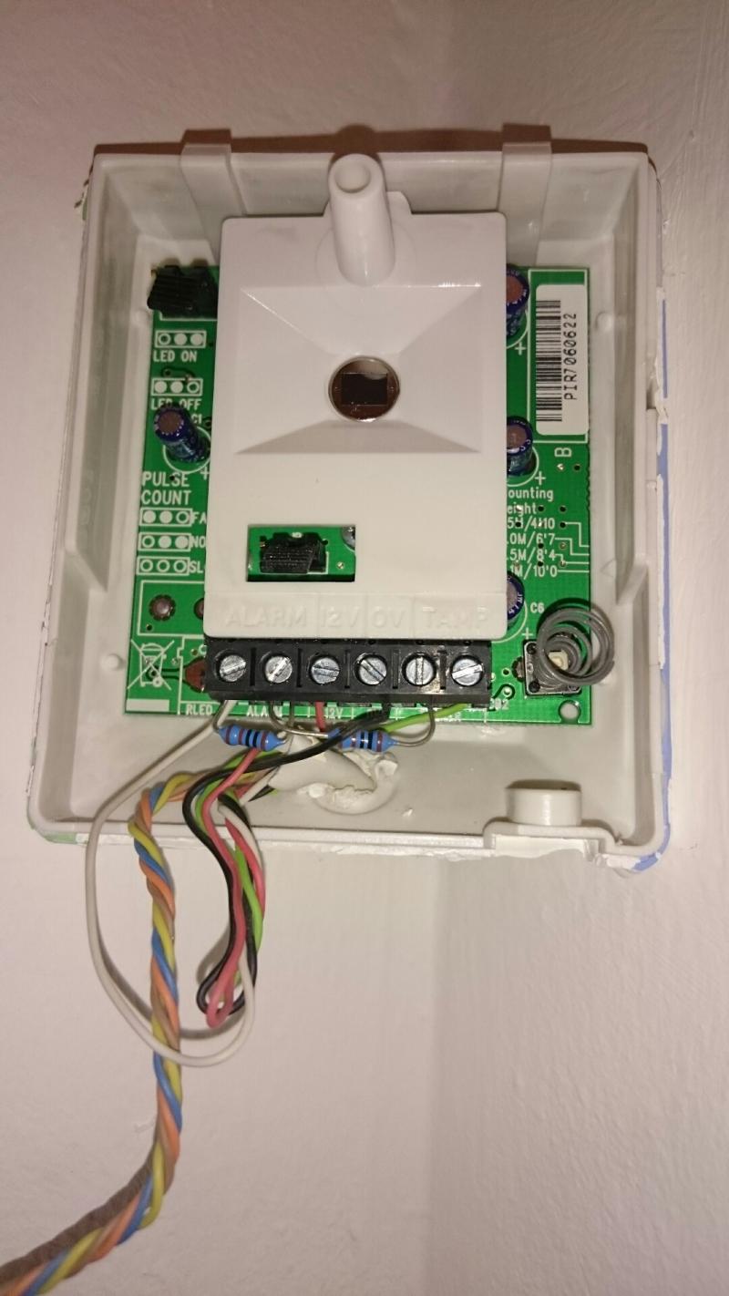
From what I can see in the pir:
Red is 12v (I normally use white)
Black is 0v (I normally use green)
White is alarm 1 (I normally use red/black)
Green is on tamper 1 (I normally use blue/yellow)
then it goes like:
there are two resisters:
1. A resister wired from alarm 1 (with white wire) to alarm 2
2. Another resister wired from alarm 2 to tamper 2
Searching I think this is to do with FSL wiring (which I guess this alarm must be) rather than CCL?
So I've bought a texecom reflex, will this have the resisters built in so I can simply drop the resisters and wire it FSL with two to 12/0v, leaving one wire in alarm and one in tamper? But looking at the photo the two resisters are the same impedance not two different values as I'm finding on the internet.
Thanks. Picture should be below/attached.
If this is the case, what's the difference between FSL and CCL alarms? Seems like more hard work with the FSL way.
I've went to replace a PIR but found this wiring setup. Can somebody help explain.
From what I can see in the pir:
Red is 12v (I normally use white)
Black is 0v (I normally use green)
White is alarm 1 (I normally use red/black)
Green is on tamper 1 (I normally use blue/yellow)
then it goes like:
there are two resisters:
1. A resister wired from alarm 1 (with white wire) to alarm 2
2. Another resister wired from alarm 2 to tamper 2
Searching I think this is to do with FSL wiring (which I guess this alarm must be) rather than CCL?
So I've bought a texecom reflex, will this have the resisters built in so I can simply drop the resisters and wire it FSL with two to 12/0v, leaving one wire in alarm and one in tamper? But looking at the photo the two resisters are the same impedance not two different values as I'm finding on the internet.
Thanks. Picture should be below/attached.
If this is the case, what's the difference between FSL and CCL alarms? Seems like more hard work with the FSL way.
Untitled
- walkern
- 1

")