Multi zone, valve and pump wiring

Joined
16 Dec 2018
Messages
9
Reaction score
0
Country
United Kingdom
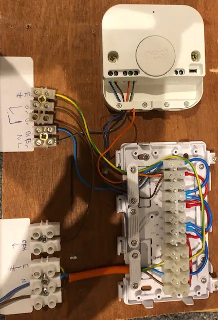
I’m hoping someone might be able to help me out with a wiring diagram.

The system runs off a combi boiler.

There is a main house radiator circuit.

There are two additional zones with underfloor heating, each with its own pump and isolator valve.

Each of the three zones has its own thermostat.

I want a valve to open, the pump to run and cfh from the boiler only when the thermostat for that zone activates.

I have a plan in my head; I’m just convinced it’s right. I’m cautious I don’t want other zones to activate additional pumps.

I’ve found many wiring diagrams on the web, but none that feature multi pumps.

If you have a diagram to share it would be appreciated.
 
Sponsored Links
Yes; appreciated. Each zone has a relay activated by the stat.

Each Drayton valve also has a relay micro switch available to use.

I’m cautious though if they all go back to a single cfh, I don’t want each zone to power other pumps.

Does someone have a diagram I could use to make this simpler.
 
Here's the basic concept. There may be some minor variations, if for example your thermostats need a neutral connection. The motorised valves contain a microswitch to allow them individually to control the boiler without feeding back to the other heating circuits and switching them on.

Drawing1 Model (1).jpg
 
Last edited:
Sponsored Links
I think that answers what I was after; thank you.

The thermostats are simple nest heat links. They make or break the chf wire from the boiler.

The aux switch allows for the circuit isolation if I underestimate correct. You get my concern that the other circuits would have been back fed by the one active circuit.
 
The thermostats are simple nest heat links. They make or break the chf wire from the boiler.

Nest's are programmable thermostats. (you just said "thermostats" which are different. Thermostats don't include any time control) That just means that there won't be any separate programmer / time control that I have shown, and the Nest Heat Links will need a neutral connection.

In your case, Heat links don't "make or break the chf wire from the boiler", they provide 230V to control the motorised valves and UFH pumps. Then the motorised valves' internal microswitches control the boiler. Either by wiring them to 230V as per my diagram, if that's appropriate, or alternatively the microswitches can be used as 'voltage free' contacts if your boiler is currently wired to use low voltage (24V) control.

The aux switch allows for the circuit isolation if I underestimate correct.
I think you mean 'understand' and if so, yes that's right.
 
I did mean understand lol.

Thanks - that’s very helpful. I simplified some of my language.

The background is, it’s an old installation that didn’t work very well. The installer effectively put the ufh on the same thermostat as the radiators. This of course meant that the radiators fired needlessly for four hours a day while the ufh was gearing up or the house was freezing working the other way round.

I improved this a couple of years ago my adding a second heat link and valve to isolate the rads use. My wiring design back then wasn’t ideal as it ‘enhanced’ the original installation.

But now with a new house extention and another ufh with its own pump and isolator the design is more complicated (for a novice at least).

I know the boiler cfh expected 230v

If I understand correctly the cfh function should always be activated by the aux switch on the valve.

The valves should be powered by the heat link circuit making contact.

A bit of a guess, but I imagine it also should happen like that to ensure the boiler doesn’t start pumping until the valve has opened and there is somewhere for the water to pump to.
 
The pump combined with the boiler that circulates water around the radiators and also supplies the UFH circuits won't start until a motorised valve is fully opened which is the point when the microswitch is operated. If your boiler has a pump overrun facility (where the pump runs for a while after the heating shuts down) then there will be a by-pass to allow the water to circulate anyway.

I have only worked on a couple of UFH systems, but on those I did, the UFH manifold allowed the UFH pump to circulate water around the UFH loop even if the motorised valve supplying it from the boiler is closed, but as the valve and pump are powered together there will only be a few seconds delay between the pump starting and the valve opening anyway.
 
Last edited:
Gotcha.

The individual zone ufh pumps do allow flow even when they’re not running effectively allowing a bit of flow when the boiler pump is powering the radiators. The zone valves were more intended to stop the radiators heating unnecessarily when the ufh was working harder and longer.

I’ll see if I can draw this out for my sanity and then maybe get back to you. Thanks for your help.
 
The water leaving your boiler will be supplied hot enough for the radiators, however this would be too hot for UFH.

The UFH pump circulates water around the UF pipes at a much lower temperature which it achieves by the manifold mixing the cooler return water from the UF pipe system with some hot from the boiler as and when required.
 
I've tried to mock it up on a board with just 1 as it's easier than working in the loft. Hopefully you can see the detail. Would this work? I think in short I have used the nest switched live to power the valve which then goes back to the shared neutral and the aux switch in the valve powers the cfh wire. Should the zone pump share the same live and neutral that goes into the valve?
 
I've tried to mock it up on a board with just 1 as it's easier than working in the loft. Hopefully you can see the detail. Would this work? I think in short I have used the nest switched live to power the valve which then goes back to the shared neutral and the aux switch in the valve powers the cfh wire. Should the zone pump share the same live and neutral that goes into the valve?
I suggest you employ the services to someone who actually knows what they are doing.
The above shambles of a mock-up would have the pump running 24/7.
 

DIYnot Local

Staff member

If you need to find a tradesperson to get your job done, please try our local search below, or if you are doing it yourself you can find suppliers local to you.

Select the supplier or trade you require, enter your location to begin your search.


Are you a trade or supplier? You can create your listing free at DIYnot Local

 
Sponsored Links
Back
Top