Nest 3rd Gen With Myson Valved System (Worcester Boiler)

Joined
17 Nov 2008
Messages
59
Reaction score
1
Location
Warwickshire
Country
United Kingdom
Hi all,

I just pruchased 2 nest 3rd gen thermostats frm screwfix on a deal. The system i want to wire these up to is a valved system. I have a thermostat upstairs and downstairs.

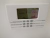
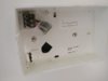
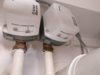
They are Myson thermostats are battery powered , using what looks like a relay and a comm wire to switch the myson valves.

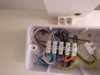
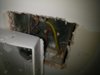
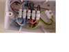
The myson valves are then wired into a box on the wall that also seems to be wired into the bioler and the comm wirs from the thermostats.

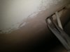
Obviously this set up is a little more complex than other i can find online. I am pretty good with basic home wiring, but i'm not sure where to start on this one. Pictures of the set up attached.
 

Attachments

  • IMG_20180220_143823.jpg
    IMG_20180220_143823.jpg
    102.9 KB · Views: 83
  • IMG_20180220_143845.jpg
    IMG_20180220_143845.jpg
    93.1 KB · Views: 110
  • IMG_20180220_144409.jpg
    IMG_20180220_144409.jpg
    140.1 KB · Views: 86
  • IMG_20180220_144416.jpg
    IMG_20180220_144416.jpg
    120.6 KB · Views: 79
  • IMG_20180220_144424.jpg
    IMG_20180220_144424.jpg
    82.9 KB · Views: 84
Sponsored Links
A couple more pics. Behind the existing thermo, there is a spare unused live wire and earth. These show up in the junction box at the other end. I think this is good news as i can use these to power the nests in their place.

The second pic shows the 2, 3 core and earth cables arriving at the back of the jucntion box, power in and the round cable runs to the boiler.

i think this is a case of sending power from the heat link to the nest thermostats through the existing wiring, then replacing the existing comm links (black and grey) in the junction box to the heatlink to talk to the valves\boilder. Just not sure?
 

Attachments

  • IMG_20180220_152622.jpg
    IMG_20180220_152622.jpg
    175.6 KB · Views: 81
  • IMG_20180220_152135.jpg
    IMG_20180220_152135.jpg
    123.2 KB · Views: 79
So having done a bit more research. The brown brown wire to my myson valves goes to the exiting thermostats, and according to the myson manual, thats the correct wire. So.. here is what i plan to do (remembering i have 2 nests and 2 valves all in this junction box. on the pic marked up...

Remove wire 1a and 2a from the junction box. Connect 1a and 2a to T1 and T2 on the 1st heat link, to send 12v power to the 1st thermostat. Also connect earth
Remove wire 1b and 2b from the junction box. Connect 1b and 2b to T1 and T2 on the 2nd heat link, to send 12v power to the 1st thermostat. Also connect earth

Connect a new wire to L where 1a and 1b were, then connect that to L on the 1st heat link
Bridge L and 2 on the 1st heatlink.

Connect a new wire to L where 1a and 1b were, then connect that to L on the 2nd heat link
Bridge L and 2 on the 2nd heatlink.


Connect a new wire to N then connect that to N on the 1st heat link
Connect a new wire to N then connect that to N on the 2nd heat link


Connect 3 on the 1st heatlink to where 2a was, which means its connected to V1 (the brown wire on the 1st myson)
Connect 3 on the 2nd heatlink to where 2b was, which means its connected to V2 (the brown wire on the 2nd myson)

Hook up the 1st thermostats at the other end of 1a 1b and earth

Hook up the 2nd thermostat at the other end of 2a 2b and earth


Job done.

Thoughts?
 

Attachments

  • Untitled.png
    Untitled.png
    1.4 MB · Views: 70

DIYnot Local

Staff member

If you need to find a tradesperson to get your job done, please try our local search below, or if you are doing it yourself you can find suppliers local to you.

Select the supplier or trade you require, enter your location to begin your search.


Are you a trade or supplier? You can create your listing free at DIYnot Local

 
Sponsored Links
Back
Top