Nest Gen 3 Install

Joined
3 Oct 2009
Messages
6
Reaction score
0
Location
Coventry
Country
United Kingdom
Hi, I want to replace my existing programmer and thermostat with a nest. My set up is as follows:

Ideal ICOS HE15 Boiler (hot water taken in airing cupboard)
Honeywell ST9400C programmer next to boiler in kitchen
3 amp fuse switch next to programmer
Honeywell T40 thermostat

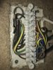
The airing cupboard does have a wiring centre with 2 cables coming in from the floor (assume mains power and boiler) and 4 cables coming out. 1 connects to the thermostat on the outside of the water tank, 1 connects to the pump and the other 2 connect to pipes that go into the HW tank??? As such, I don't think the wiring centre comes into play.

I've attached pics of the current wiring.

The N & L on the programmer have 3 wires into each, I'm guessing:

1 - there is a power switch to provide/cease power to the bolier and programmer
2 - the second set goes to the bolier to provide power there
3 - the 3rd set goes to the old thermostat

Terminals 1/2 on the programmer have no connection. T3 is Hot Water On and T4 is Heating On, so these go to 6/3 on the heatlink.

I assume that I work out which cable to N/L feeds the thermostat and move these to the T1/T2 on the heatlink and then corresponding T1/T2 on the nest thermostat. Or is the third set actually feeding the Hot Water wiring centre? If so where is the connection to the thermostat.... is that going direct to the boiler?

Reading the following link, it looks like I need to add a cable to hook up the L to the com connection for HW and Heating.

The only thing I can't get my head around.... with the current wiring, how does the thermostat actually work???

Does this sound right?

Thanks

EDIT, there's actually 3 cables going into the wiring centre, I've attached a pic of that. Nest Heatlink.jpeg Programmer Wiring.jpg ST9400 Diagram.jpeg Thermostat Diagram.jpg Thermostat Wiring.jpg
 

Attachments

  • IMG_3428.jpg
    IMG_3428.jpg
    325.8 KB · Views: 334
Last edited:
Sponsored Links
Okay, so looking at the wring centre, I can see two cables coming into the same connector, but nothing going out on the other side. So is this a cabe from the thermostat and a cable from the boiler?

wiring centre.jpeg
 
Okay, so I can now see that the thermostat goes into the wiring centre. Would this action be correct?

Remove the thermostat cable completely from the wiring centre and connect the boiler cable from T4 on the 'in' side to T5 on the 'in' side so that it is directly connected to the Heating valve.

My challenge then is how I get 12v to the nest thermostat or will I have to use the external power supply for the nest thermostat?

Something like this to take a 240v from the wiring centre to the thermostat cable https://www.amazon.co.uk/Leyton-Lig...coding=UTF8&psc=1&refRID=9FK3KZS0FGS8G63RAAYJ
 
Last edited:
What you don't tell us is what is actually operating the system, most systems have a motorised valve or two that are switched by the thermostats to control where the flow of water goes ie to the radiators or hot water system. There are two types commonly used. One uses a single 3 port valve to direct the water to where it's required, but with this solution, there would be a wire connected to terminal 1 (Hot water off) as this wire isn't present I suspect that you will have the other version with two, 2 port motorised valves.

They look something like this:


Is this what you have?
 
Sponsored Links
Thanks

In that case, whilst installing the Nest will not be particularly difficult to someone that understands circuits and is electrically competent; some of your comments, especially those asking how does the existing thermostat work, and whether you need to add a lighting transformer to power the Nest thermostat worry me a bit.

If you don’t understand clearly what is written below, then I would recommend that you get it professionally installed. Get it wrong, and you can cause expensive damage…..or worse!

HEATLINK

OK; so as you have worked out the wires currently going to

Terminal 3 at the ST9400C will go to terminal 6 at the Heatlink (Hot water call for heat)

Terminal 4 at the ST9400C will go to terminal 3 at the Heatlink (Heating call for heat)

Then you need to connect all of the live wires currently connected to the ST9400C to the live at the Heatlink, and also to the Heatlink common terminals (numbered 2 and 5) Logistically it won’t be possible to get them all physically in one terminal so you may have to distribute the live wires across all three terminals, or even add additional terminals but all 3 must all be electrically connected.

The neutrals from the ST9400C connect to the Heatlink neutral.

Earth wires into the earth terminal as applicable.

The Heatlink is now installed.

NEST THERMOSTAT

The new Nest thermostat can be powered by one of two methods, either by using a separate plug in power supply provided by Nest, or by connecting it to the Heatlink terminals T1 & T2 provided for this purpose. You don’t need any additional power supply or transformer to do this. T1 at Heatlink goes to T1 at the thermostat and T2 at the Heatlink goes to T2 at the Thermostat.

REMOVING THE EXISTING THERMOSTAT

Because the Nest carries out the functions of the room thermostat, the old wired thermostat needs to be 'decommissioned' to prevent it interfering with the operation of the Nest. Find the opposite end of the thermostat cable to the thermostat end at the wiring centre. Note carefully which terminals at the wiring centre that the Brown and Black wires from the T40 terminals 1 and 3 came from remove the cable and link the two terminals noted above together.
 
Last edited:
Thanks that makes sense and was my understanding. The comment relating to the transformer is that the T40 thermostat is in the hallway and the programmer in the kitchen, so there isn't a cable to allow me to hook up T1/T2 of the heatlink to the nest thermostat (without major rewiring!!).... hence my thoughts of utilising the redundant T40 cable to provide the power... but of course needed to convert it from providing 240v down to 12v.
 
Ah OK, thanks for the clarification I understand what you are thinking now.

Whilst the existing thermostat cable can be used to connect the 12V to the Nest Thermostat. Usually, as in your case, it runs to the wiring centre and not the programmer, so it either means extending the wiring centre end of it to the Heatlink, or running a separate new cable. Running a new cable might not be as difficult as you first imagine. As it is only 12V the thinner cable used for installing alarm systems can be used which is easier to install.

Others have asked about using a separate power supply for the thermostat in the past, but the consensus is that whilst it could be done in theory, it would not be recommended, whilst the voltage maybe OK, the level of smoothing provided, or the protection from spikes etc., might not be good enough for sensitive electronics.
 

DIYnot Local

Staff member

If you need to find a tradesperson to get your job done, please try our local search below, or if you are doing it yourself you can find suppliers local to you.

Select the supplier or trade you require, enter your location to begin your search.


Are you a trade or supplier? You can create your listing free at DIYnot Local

 
Sponsored Links
Back
Top