Nest Installation Issues

Joined
27 Sep 2008
Messages
21
Reaction score
1
Location
Buckinghamshire
Country
United Kingdom
Morning,

I am about to install a Nest Thermostat (3rd Gen) and after looking at what I currently have, there's a couple of queries.

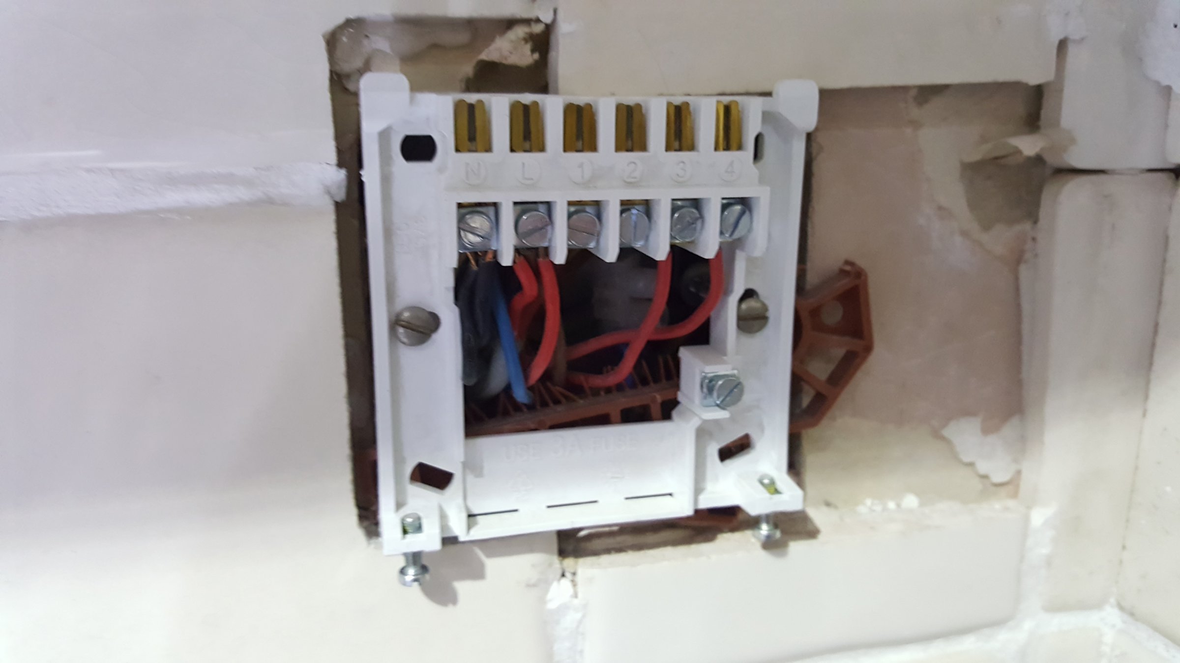
Issue 1: Current Controller has N L 1 2 3 4 and is wired as follows:

N - 3 Wires: 1 is from the fused switch, 1 goes to the boiler and I have another mystery wire which I think is the thermostat ? (more on that in a moment)

L - 3 Wires: Same as above

1 - Nothing

2 - Nothing

3 - Red wire, controller says this should be Central Heating Out

4 - Red wire, controller says this should be Hot Water Out

On the Nest Heat Link I have N L 1 2 3 4 5 6 OT1 OT2 T1 T2 - What should go where?

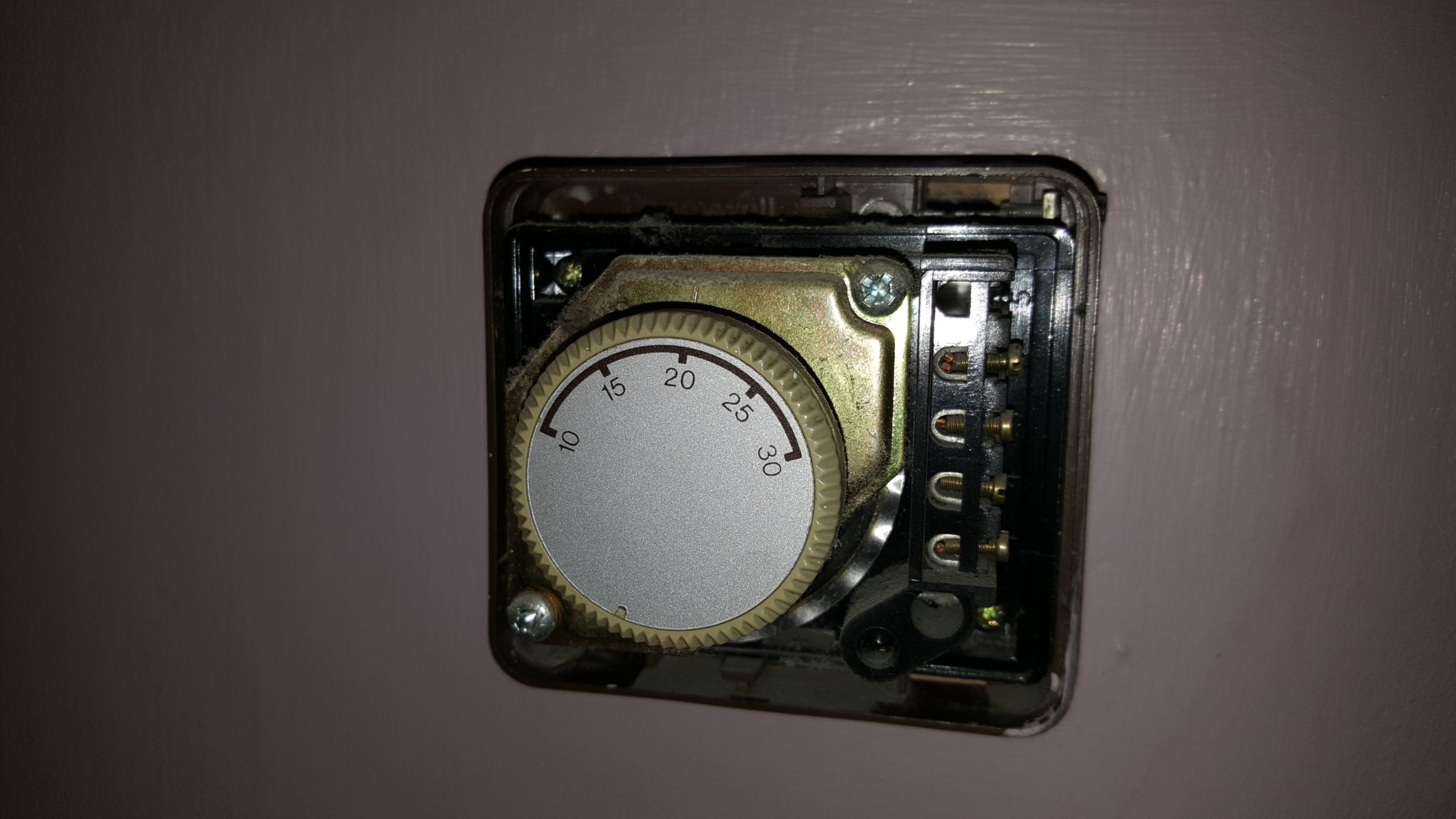
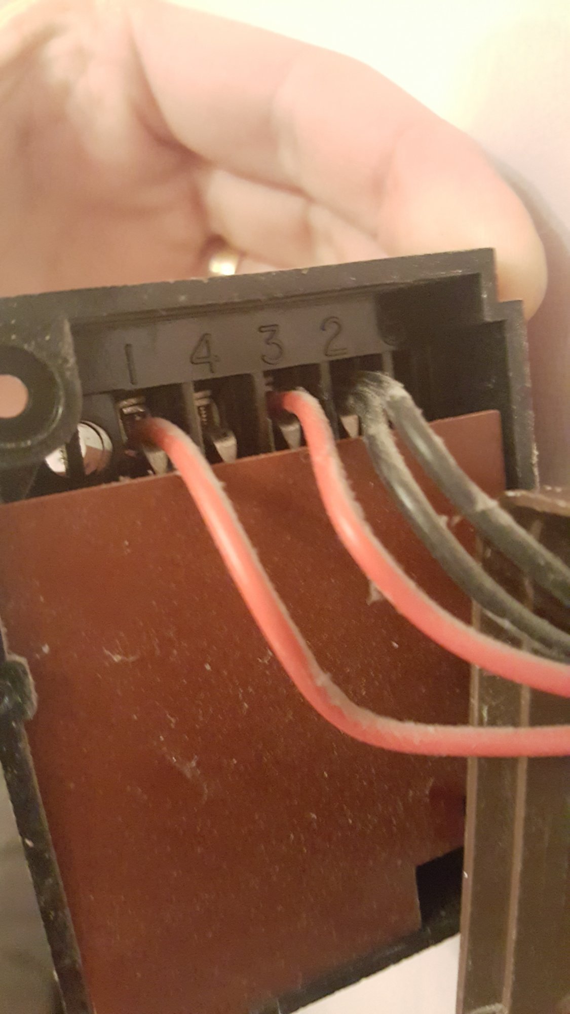
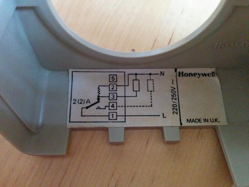
Issue 2: Thermostat has 4 wires going to it, a Red Wire into 1, a Red Wire into 3, and the 2 Neutrals into 2

Presume this means they are high voltage and I shouldn't plug straight into the thermostat? If so, my question is - where do these 4 wires run back to? Are the two mystery wires in the controller for this? Where do the other 2 wires go? Can I take these out of the equation and wire into T1 and T2 on the heat link ?

Appreciate any helpful advice.
 
Sponsored Links
First of all the existing wired in thermostat needs to be removed. You need to trace its wires back to their origin and remove them. Then the two switching wires originally going to the thermostat should be joined together (usually at a wiring centre) Then follow the wiring diagram shown in the Nest manual as follows:

The Heatlink replaces the existing programmer and
1. The current 'Central Heating on' wire goes to the Nest 'Heating Call for Heat' (3)
2. The current 'Hot Water On' wire goes to the Nest 'Hot Water Call for Heat' (6)
3. The wires in the current 'L' go to the Nest 'L'
4. The wires in the current 'N' go to the Nest 'N'
5. Link the Nest 'L' terminal to the Heating and Hot water Commons (2 & 5)

The new Nest thermostat can get its power supply by either wiring it to terminals T1 & T2, at the Heatlink, or powering directly from a mains adaptor

OK Thanks for this. However, I am a bit stuck on step 5. Do you mean run a wire from L on the heat link into both 2 & 5 ?
 
Do you mean run a wire from L on the heat link into both 2 & 5 ?
Yes, both 'commons' need a live supply otherwise you won't have any power to the heating and hot water control switches. See the image below from page 24 of the installation manual. You will see L, 2 and 5 linked together. You should have received this document with your Nest.
 

Attachments

  • 3rd-gen-Nest-Learning-Thermostat-Install-Guide-UK.pdf
    45.1 KB · Views: 223
Last edited:
Sponsored Links
Yes, both 'commons' need a live supply otherwise you won't have any power to the heating and hot water control switches. See the image below from page 24 of the installation manual. You will see L, 2 and 5 linked together. You should have received this document with your Nest.

Ah yes, I did receive that thanks. Makes sense now!

On the thermostat side of things - are the 2 mystery wires for the Thermostat? Are these the ones I would need to join together? Any ideas where the other 2 wires might go? Could I in anyway use the existing cabling for the new thermostat ?
 
Can you trace each of the 4 wires and say what they are connected to?

Also the make / model of the thermostat would be useful. Or a photo of any wiring diagram. Sometimes there is one inside the lid. Without that information the thermostat terminal numbers you give (1, 2 & 3) are meaningless. I could make a guess based on the colours, but that all depends upon the person that installed it originally and the colours they decided to use.
 
Ok so this is the Thermostat:
And here is the wires:
Just for clarity, this is how the programmer was wired
I can't trace the wires easily as the thermostat is in the lounge, the wires run into the back box and I'm just guessing as to where they go. Don't understand why I've got 4?
 
OK it's a mechanical Honeywell thermostat, so it will require 3 wires. There is usually a wiring diagram inside the cover, however it has a live supply from the programmer, a switched live to start the heating running and a Neutral. The Neutral is there for a small 'accelerator' device to improve the accuracy of the old mechanical technology.

So, I believe (but cannot confirm without a diagram of the thermostat internals) that the three wires are as follows:

Live in from the programmer (Terminal 1)
Neutral (Terminal 2)
Live out to central heating (Terminal 3)

The question is where does the second neutral wire go? Unfortunately only you can tell us by tracing it. It may go to the heating motorised valve, if so the two neutrals will need to remain connected together.

You will still need to find the other end of the wires to disconnect it from the existing system and insert a link between the switching wires. The switching wires are the two red ones in terminals 1 & 3 when you disconnect the thermostat cable at the other end the two cables that they go to need connecting together.
 
Ah good, then that confirms that my assumptions were correct:

Live in from the programmer (Terminal 1)
Neutral (Terminal 2)
Live out to central heating (Terminal 3)

You just need to find the other end of the wires now.
 
Ah good, then that confirms that my assumptions were correct:

Live in from the programmer (Terminal 1)
Neutral (Terminal 2)
Live out to central heating (Terminal 3)

You just need to find the other end of the wires now.

Excellent advice so far, thank you.

Will one of the Neutrals will also go back to the programmer? I am also guessing that the live out to central heating and the other neutral possibly go to the motorized valve ? Will this be likely in the airing cupboard ?
 
Will one of the Neutrals will also go back to the programmer? I am also guessing that the live out to central heating and the other neutral possibly go to the motorized valve ? Will this be likely in the airing cupboard ?
Quite likely. There is usually a wiring centre somewhere and all of the cables usually go back to that.
 
Quite likely. There is usually a wiring centre somewhere and all of the cables usually go back to that.
OK - there is a wiring centre under the pump in the airing cupboard. 95% sure that's where the other leads on the thermostat are going, as there is no power to the pump when I isolate the power at the programmer.

So, am I right in thinking if I join the Neutrals together, join the Lives together and then wire the live into the call for heat on the heat link - that will do the trick ?
 
Pretty much. When you remove the wiring going to the thermostat from the wiring centre, where the wires that went to thermostat terminals 1 & 3 were, you need to insert a link between them.

The neutrals might be a bit more tricky because they might not both go to the wiring centre [they might. It all depends upon the personal preferences of the installer] one possibly will go to the motorised valve. If so, somehow you need to maintain the continuity of the Neutral, so it might mean a new wire from the wiring centre to the motorised valve. But we can't know for sure until you have determined where they go.

As an alternative, the easiest way would be to remove the thermostat and link the two neutrals together, and the two lives together. That way you can leave the wiring centre as it is. The problem here though, is that you will have to leave a junction box on the wall where the thermostat presently is. But if you don't mind that being on show, it would be the easiest way.
 
Last edited:

DIYnot Local

Staff member

If you need to find a tradesperson to get your job done, please try our local search below, or if you are doing it yourself you can find suppliers local to you.

Select the supplier or trade you require, enter your location to begin your search.


Are you a trade or supplier? You can create your listing free at DIYnot Local

 
Sponsored Links
Back
Top