Nest installation

Joined
25 Nov 2018
Messages
4
Reaction score
0
Country
United Kingdom
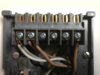
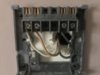
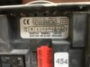
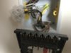
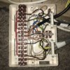
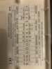
Hi, I am replacing my current thermostat and timer which are danfoss, my boiler is an Ideal logic and I believe it’s a Y plan ( I could see only 1 motorised 3 way valve at the pump and hot water tank). I assumed it would be an easy enough install but find it hard to trace back wiring there is also an electrical junction box at the hot water tank. My query was where does the heat on wire feed back to the pump or the timer, I was going to use the live and neutral from the thermostat to power up the nest. Please see enclosed pics, the second last pic is the wiring to the timer the 4 wires that are in the terminal block ? and coiled up behind there is a brown and black with bare ends ? Any pointers would be greatly appreciated.
 

Attachments

  • 82134AA2-0833-4A6E-BCB8-9909390B1183.jpeg
    82134AA2-0833-4A6E-BCB8-9909390B1183.jpeg
    174.3 KB · Views: 431
  • DEA74847-46F0-4191-B3C5-A91A1CD67D1C.jpeg
    DEA74847-46F0-4191-B3C5-A91A1CD67D1C.jpeg
    180.6 KB · Views: 292
  • 6938F9FC-D37D-4463-B97A-76E7F7795336.jpeg
    6938F9FC-D37D-4463-B97A-76E7F7795336.jpeg
    194.5 KB · Views: 251
  • A4E2615F-494B-460A-8588-E99B88720C64.jpeg
    A4E2615F-494B-460A-8588-E99B88720C64.jpeg
    189.3 KB · Views: 261
  • 622C0AD4-B846-437B-AB01-2455AC711CF1.jpeg
    622C0AD4-B846-437B-AB01-2455AC711CF1.jpeg
    181.3 KB · Views: 266
  • 7C8896EF-4521-4B43-A130-C65D57EDADFD.jpeg
    7C8896EF-4521-4B43-A130-C65D57EDADFD.jpeg
    137.4 KB · Views: 409
  • C5B42512-0843-4857-A480-304A33797867.jpeg
    C5B42512-0843-4857-A480-304A33797867.jpeg
    506.1 KB · Views: 279
  • 5C3110FD-3573-4F98-9D15-6A87E9C816BE.jpeg
    5C3110FD-3573-4F98-9D15-6A87E9C816BE.jpeg
    262.7 KB · Views: 278
Last edited:
Sponsored Links
Sponsored Links
Must admit it is getting so tedious now, Hive and nest should have their own forum called "Its a feckin switch"
 
Don't worry boys, Stem will be along soon to sort it out
I resemble that statement!

OP, the Nest Heat link replaces the existing programmer. As has been said previously, you are erm....just replacing a switch with another.

1.JPG
The wires in the programmer L go to Heat link (L)
The wires in Programmer N go to Heat link (N)
The wire in Programmer 3 goes to Heat link (6) Hot water call for heat
The wire in Programmer 4 goes to Heat link (3) heating call for heat
Also connect together Heat link terminals (L) (2) & (5)

The Nest thermostat can be powered by wiring it to the Heat link terminals T1 & T2, or by using a separate Nest plug in power supply.

You will also need to decommission the existing room thermostat.

2.JPG
If you are happy to leave it in place, then just move the wire from L and put it in 3 with the wire that is already there. If you want to get rid of the original thermostat; trace the cable from the thermostat back to its origin, disconnect all three wires and then join together the terminals that you have just removed the brown (L) and black (3) wires from.
 
Thanks Stem,
I have a mechanical background, when it comes to tracing wires etc that's my weakness. I was intending to mount the new stat where the existing stat is located, I realise that it requires 24v supply, can I use the wires from the old stat to power it? or would I need to run new cable. I was going to wire the heatlink where the existing programmer is situated, I am unsure about the wiring for T1 and T2 at this location or would I need to site the heatlink at the junction box at the tank with all the terminals 1-16 ?

Many thanks

Del
 
The Nest thermostat needs 12v which can come from T1 & T2 (not 24v. I think you may be looking at the Open Therm terminals)

You can use the old cable to provide power to the thermostat it but only once it has been completely disconnected from the mains wiring. More often that not though, it doesn't go to where the Heat link is located so isn't always that much use. It looks possible that it may go to terminals 2 and 3 of the wiring centre, as per the label as it appears to be connected to a brown wire going to a motorised valve via the red link. Hopefully the heating motorised valve. (installers don't always follow the pre- printed label)

If you want to site the Heat link near the wiring centre you can but you will have to disconnect the wires from the programmer and then wire the Heat link in in there place. So you will be pretty much re-wiring the system. I wouldn't recommend that for DIY there is too much scope to get something wrong.
 
Last edited:
Thanks again,
If It does look like you say, that the original stat wires go to 2 & 3 in the wiring centre, is there any way I can connect from the wiring centre and tie it into the wiring centre that goes to the programmer? Hmm. If not it is looking like my option is to forget wiring T1&T2 then disconnecting the old stat and using the nest via a 240 plug/usb etc. But just to clear things up with me being a spanner monkey to decom the existing stat (which I’d leave in place ) I only have to move only have to move the live wire and wire it in with the black on the stat and just leave all the rest in place as in no need to disconnect at the wiring centre? Er what does this do or prevent? Just curious thanks
 
Last edited:
Thanks again,
If It does look like you say, that the original stat wires go to 2 & 3 in the wiring centre, is there any way I can connect from the wiring centre and tie it into the wiring centre that goes to the programmer?
Once the old thermostat cable has been completely removed from the wiring centre, you can put it in a junction box and connect a new cable to extend it to the Heat link if you like.

to decom the existing stat (which I’d leave in place ) I only have to move only have to move the live wire and wire it in with the black on the stat and just leave all the rest in place as in no need to disconnect at the wiring centre?
Yes that is correct, but the cable will still have 230V on its brown and black wires, so you won't be able to it for the 12v connection.

Er what does this do or prevent? Just curious thanks
Electrically speaking there is no difference between the two solutions, it is exactly the same thing. With one the link is actually in the wiring center. With the other the wire goes out from the wiring centre to the thermostat where the link is made (by putting both wires in the same terminal) and then back to the wiring centre. It's just a very extended link.

The advantage of removing the old stat just means that you won't have a function less item on your wall, and you can possibly re use the wire for T1 & T2 if its buried in the wall.
 

DIYnot Local

Staff member

If you need to find a tradesperson to get your job done, please try our local search below, or if you are doing it yourself you can find suppliers local to you.

Select the supplier or trade you require, enter your location to begin your search.


Are you a trade or supplier? You can create your listing free at DIYnot Local

 
Sponsored Links
Back
Top