Outdoor sensor light wiring?

Joined
24 Apr 2021
Messages
8
Reaction score
0
Country
United Kingdom
8C37B654-9233-4D18-BA15-2DF06EA87893.jpeg
72F78113-B9E5-4D5C-A288-AD7894D69AAE.jpeg
Hi, I’ve just wired up a new lighting circuit and have wired in an outside up/down wall light with motion sensor. Attached are pics of how I’ve wired up. It turns on at the switch but when turned off the sensor doesn’t seem to be working?

the wiring on the right is the feed from fuse box and 3 core and earth is to the light... second picture is the wiring in the light fitting

cheers
 
Sponsored Links
Hi Ashmarch94,

Can you upload a copy of the instructions for the light?

It looks like the brown core and black core on the light fitting are mixed up, but need to confirm with the instructions.

Also the black cores should be sleeved brown and the grey cores should be sleeved blue on both ends.

Regards,
Huggybear.
 
Looks right to me, check the settings on the sensor
Thinking aloud .... and assuming that the black and brown of the 3C+E are the L and S/L of the PIR (one way around or the other), then, wired per the photo, as far as I can see ...

If the brown is the L (and black the S/L), then the PIR would be permanently powered (with switch in either position), and switching the switch 'on' would over-ride the PIR and turn the light on permanently - which I suspect is what the OP wants. If that IS what he wants, then, given that the wiring would seem correct to supply power permanently to the PIR, as you say, he should check the PIR settings (e.g. maybe he was testing during daytime, but it was set not to work in daylight).

On the other hand, if the black is the L (and brown the S/L), then (with wiring per photo) the light would be permanently on (with switch in either position). The PIR would only be powered when the switch was in the 'on' position, but that wouldn't change anything, since the light would be permanently on (with switch in either position), anyway.

.... which I suppose all boils down to a waffly way of agreeing which what you said (in just 10 words) :) .

Kind Regards, John
 
Sponsored Links
The braided cables are heat resistant usually due to the fact they used to go to the hot Rx7 lampholders, maybe still do, therefore by default the Red and the connecter can only be the Pir output.
This seems quite a standard set up.
At his switch the supply is Brown and blue 2 core, so that clearly shows the 3 core Brown to be a permanent live and the Black a switched output.
As agreed it is likely a senser issue unless the Brown permanent supply is not reaching the pir terminal somehow
 
The braided cables are heat resistant usually due to the fact they used to go to the hot Rx7 lampholders, maybe still do, therefore by default the Red and the connecter can only be the Pir output. This seems quite a standard set up.
Indeed so - confirming that the black of the 3C+E is the S/L.
At his switch the supply is Brown and blue 2 core, so that clearly shows the 3 core Brown to be a permanent live and the Black a switched output.
Yes, but only IF it has been wired correctly - and we can't be sure that it is correctly wired by just looking at what happens at the switch. However, as above, what we see at the other end of the 3C+E does seem to confirm that black is S/L (hence brown is permanent L).
As agreed it is likely a senser issue unless the Brown permanent supply is not reaching the pir terminal somehow
Yes, agreed.

Kind Regards, John
 
Thanks for your responses. Yes I’ve wired it so black is switch live. And was testing it at night time. The instructions only have live, neutral and earth. Nothing about switch lives...

switch turns light on and off as I want but just the sensor not working for some reason. Settings are correct too
 
Thanks for your responses. Yes I’ve wired it so black is switch live. And was testing it at night time. The instructions only have live, neutral and earth. Nothing about switch lives...
In 'normal use' there is no need for a switched live, which is perhaps why the instructions don't mention it. Some do not have such a connection, and most of the modern 'integrated' LED ones 'cannot' (because of the way they are designed and manufactured) offer such a connection.

The S/L is only needed/used if one wants to run additional light(s) (additional to those in the unit itself) off the PIR sensor and/or if (as in youyr case) one wants to have a switch which turns the light(s) on continuously (i.e. over-riding the sensor).
Yes I’ve wired it so black is switch live. And was testing it at night time .... switch turns light on and off as I want but just the sensor not working for some reason. Settings are correct too
OK, so the wiring is correct, but the sensor (which should be permanently receiving power, even with switch off) is not doing what it should. I think Rocky has already mentioned most of the possible explanations (other than the unlikely possibility that you simply have a faulty sensor!).

For what it's worth, when I have been in the position of thinking that a PIR sensor was not working, it has usually been due to my having (sometimes because of poor instructions and/or labelling/marking) 'got the settings wrong' (turning the 'sensitivity' or 'light level' adjusters fully in the wrong direction for my test!).

Assuming you are sure that there is no such problem, the next question is whether you have a multimeter or other means of detecting voltage, since the most logical next thing to do it so confirm that voltage is actually getting to the light/sensor (along the brown of your 3C+E). It's hard to see how it could be failing to do so - but one thing to check (without needing to do any measurements) would be to make sure that, at the 3-way connector block for the light, the screws for the left hand section (joining the browns) are both tightened onto the copper conductor (and not onto the brown insulation!!). It wouldn't be the first time that someone had managed to make that mistake!

Kind Regards, John
 
Thanks guys, have put the red braided cable back in as didn’t look 100% so shall see how it tests tonight... also, I have these 4 cables running through this brick wall into the consumer unit the other side, does it matter that they aren’t in conduit? (An old external wall which is now internal)
 

Attachments

  • E5C6B318-1E89-43F4-85E2-2EF6A1630462.jpeg
    E5C6B318-1E89-43F4-85E2-2EF6A1630462.jpeg
    848.6 KB · Views: 131
Thanks guys, have put the red braided cable back in as didn’t look 100% so shall see how it tests tonight...
OK - but I don't think that would have been the problem since, if the connection had been iffy, the light would not have come on with the switch 'on'. As I said, if there were a 'wiring problem' (to give the results you've experienced) it would be more likely to be in relation to those two browns which are meant to be connected together at the left of that 3-way terminal block.
...also, I have these 4 cables running through this brick wall into the consumer unit the other side, does it matter that they aren’t in conduit? (An old external wall which is now internal)
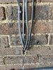
Maybe not ideal, but I don't think you should worry about that. They all ought to be clipped to wall, though, and you should avoid any tight bends where they come out of the wall.

Kind Regards, John
 
As I said, if there were a 'wiring problem' (to give the results you've experienced) it would be more likely to be in relation to those two browns which are meant to be connected together at the left of that 3-way terminal

thanks John, do you mean the browns at the light fitting terminal block? If so the brown is going into the brown?
 
Yes it is, but check both sides are screwed onto the copper rather than the insulation.
Is this a new fitting.
 
What i would be tempted to try is reversing the 3 core Brown and Black connections, both at the Light and at the switch.
Therefore Black as Permanent live and Brown as switched live.
If still works the same as previously, it will at least prove continuity on The Brown conductor, thus indicating a fault within the light unit.
 
And some units are not suitable or adding a SL feed, I've encountered failed units for this reason.

Even to the point of removing a brand new fitting, getting it replaced by the shop, installing the new fitting testing and adjusting the PIR. Then wiring SL in and the PIR stopped working.

Then changed it for a different fitting that could accept SL.
 

DIYnot Local

Staff member

If you need to find a tradesperson to get your job done, please try our local search below, or if you are doing it yourself you can find suppliers local to you.

Select the supplier or trade you require, enter your location to begin your search.


Are you a trade or supplier? You can create your listing free at DIYnot Local

 
Sponsored Links
Back
Top