Potterton EP2002 to Honeywell ST9400C

Joined
7 Mar 2018
Messages
3
Reaction score
0
Country
United Kingdom
Hi, hope you don't mind that this is my first post, but I'm in need of some help!

Tried searching the internet far and wide for a solution, and thought I had found one on this forum, but it didn't quite work for me.

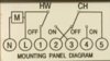
I'm trying to replace my Potterton EP2002 controller with a Honeywell ST9400C controller, as it has more features that I could make use of!

Found a thread on here and followed it word for word but it didn't quite work for me.

(https://www.diynot.com/diy/threads/swap-potterton-ep2002-for-honeywell-st9400c.327188/)

When following that guide the controller powered up however the LCD just flashed every second, and none of the buttons did much.

Is anyone able to spot an obviously solution? Or should I call a heating engineer?

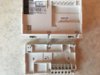
I've attached some photos.

IMG_20180307_183307.jpg IMG_20180306_170628.jpg
 
Sponsored Links
The EP2002 is a bit unusual because it is a Programmer and Wiring Centre combined. The terminals A B C & D are just terminals provided for convenient use by the installer. They are simply used to connect wires together and are not connected to the programmer functions. Your biggest problem is that the Honeywell does not have this 'junction box' facility to accommodate so many wires. To get around this, I would normally sink a single gang flush mounting socket box in the wall behind the programmer to house some additional new terminals used to replace them. Fortunately for you, it appears that you have one in place already. Please note that these instructions are based on modifying what is shown in your photos.

This extra wiring whilst not "rocket science" does mean that you need to be competent with electrical installation procedures to do this safely. If you feel unsure, please do get someone professional to do it for you.

If you are competent to proceed, you will need 2 new extra terminals to replace EP terminals B & D. Both of the wires presently contained in 'B' go into one of the new terminals, both of the wires from 'D' go into the second new terminal.

Earths from the EP2002 go to the Honeywell earth parking tether. As there are a lot, you may have to put them into a separate terminal(s) first if required, but they all do need connecting together. Make sure that the metal socket box also has an earth connection.

Neutrals from the EP2002 neutral terminal on the left go to the Honeywell Neutral. Again, as there are a lot, you may have to put them into a separate terminal(s) first if required, but they all do need connecting together.

Then it is a matter of moving the remaining wires from the main switching terminals as defined on the back of your EP2002 (N, L, 1, 3 & 4) as below


to the corresponding terminals at the Honeywell. Fortunately they are the same.

Capture.JPG


The loop from the EP Live to terminal 5 is discarded, but the remaining brown wire in terminal 5 needs connecting to the Honeywell Live
 
Many thanks for your reply. It's well written and makes a lot of sense!

I'll have a second attempt tomorrow while the sun is still up and hopefully before I need heating!

Fingers crossed there is enough space in that single gang box too!
 
Thank you for your help!

Picked up a wiring block today and fitted the new controller this morning. Didn't take too long either!
 
Sponsored Links
The EP2002 is a bit unusual because it is a Programmer and Wiring Centre combined. The terminals A B C & D are just terminals provided for convenient use by the installer. They are simply used to connect wires together and are not connected to the programmer functions. Your biggest problem is that the Honeywell does not have this 'junction box' facility to accommodate so many wires. To get around this, I would normally sink a single gang flush mounting socket box in the wall behind the programmer to house some additional new terminals used to replace them. Fortunately for you, it appears that you have one in place already. Please note that these instructions are based on modifying what is shown in your photos.

This extra wiring whilst not "rocket science" does mean that you need to be competent with electrical installation procedures to do this safely. If you feel unsure, please do get someone professional to do it for you.

If you are competent to proceed, you will need 2 new extra terminals to replace EP terminals B & D. Both of the wires presently contained in 'B' go into one of the new terminals, both of the wires from 'D' go into the second new terminal.

Earths from the EP2002 go to the Honeywell earth parking tether. As there are a lot, you may have to put them into a separate terminal(s) first if required, but they all do need connecting together. Make sure that the metal socket box also has an earth connection.

Neutrals from the EP2002 neutral terminal on the left go to the Honeywell Neutral. Again, as there are a lot, you may have to put them into a separate terminal(s) first if required, but they all do need connecting together.

Then it is a matter of moving the remaining wires from the main switching terminals as defined on the back of your EP2002 (N, L, 1, 3 & 4) as below


to the corresponding terminals at the Honeywell. Fortunately they are the same.

View attachment 137873

The loop from the EP Live to terminal 5 is discarded, but the remaining brown wire in terminal 5 needs connecting to the Honeywell Live


Hello Stem,

First of all thanks for the instructions above. I feel more confident moving forward to attempt swapping my EP2002 for THR860S (Homexpert by Honeywell). The wiring on my EP2002 is however a bit different from the other user. Moreover whoever installed appears not to have used the conventional wire colours for their corresponding terminals. Please see attached images. I would be most grateful for similar instructions for my case.
 

Attachments

  • IMG_3334.JPG
    IMG_3334.JPG
    251 KB · Views: 498
  • IMG_3339.JPG
    IMG_3339.JPG
    230.8 KB · Views: 483
Hi Biloxi26

The two wires in 'C' Yellow & Black should be removed and joined together with an insulated screw connector, do not connect them to the new programmer.

The two wires in 'D' Red & Black should be removed and joined together with an insulated screw connector, do not connect them to the new programmer.

I believe that one of the Brown wires in 'L' is connected to '5' if so remove it and discard it. If not let me know. The remaining Brown wire goes to 'L' at the new programmer, as do the remaining wires from terminal '5'

All of the wires in 'N' go to 'N' at the new programmer.

'3' is hot water on and goes to '3' at the new programmer.

'4' is central heating on and goes to '4' at the new programmer.

If anything is unclear, or you have any questions, post back.


Hi Stem
Thank you for this. I am generally clear on what needs to be done. I am looking to complete the installation tomorrow. What do you think is/should be the earthing arrangement for the step. It’s not clear from my current ep2002 wiring and not sure what it should be for the swap.

Many thanks in advance
 
The earth wire connections are not visible in your photograph. However it is likely that they have a separate connector tucked away somewhere in the box at the back. This needs to remain as it is with all the earth wires simply connected together as they are now.

The new programmer itself doesn't need an earth connection it is 'Double Insulated' (the small square inside another square next to the CE mark identifies this) so it doesn't need an earth connection.

The metal back box that is sunk into the wall should be connected to earth though.


Most grateful for your help with this Stem. Everything worked perfectly as you described. Apologies for not updating you earlier. You are a legend
 

DIYnot Local

Staff member

If you need to find a tradesperson to get your job done, please try our local search below, or if you are doing it yourself you can find suppliers local to you.

Select the supplier or trade you require, enter your location to begin your search.


Are you a trade or supplier? You can create your listing free at DIYnot Local

 
Sponsored Links
Back
Top