
I think i worded that wrong lol, with them joined together in the kitchen do u get continuity on the cable from the panel to the hall? U can actually wire each detector with 3 cores if u link 0v and com in the detector, then wire the other core to eol terminal on the panel

You are using an out of date browser. It may not display this or other websites correctly.
You should upgrade or use an alternative browser.
You should upgrade or use an alternative browser.
Pyronix Castle Euro46 v10 - Clean start, lan card, cloud link
- Thread starter GoodDIYjob
- Start date
As above it may have been junction boxed in series under the floor …twist together at both pirs ( blue and yellow ) then check at the panel end …
Hey. Yes, if blue and yellow are joined at both PIR locations, there is continuity all the way back to the panel. Reading 3ohms.I think i worded that wrong lol, with them joined together in the kitchen do u get continuity on the cable from the panel to the hall? U can actually wire each detector with 3 cores if u link 0v and com in the detector, then wire the other core to eol terminal on the panel
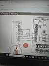
Per your wiring diagram below, I think I can probably try and and execute that, thank you. I am a bit confused about what's going on with this blue / yellow pair now... why do they need to be twisted together in both PIR locations to get continuity back to panel? No com wire required - is that because you've looped through 0v?
Yes, you've got it. I don't really understand what is going on though? 3 ohms at panel when blue and yellow twisted together at BOTH Pirs. But if either twist join is removed at either PIR, nothing back to alarm panel? I thought ok, so the feed is direct to kitchen rather than hall but why both need to be twisted together to get a reading...As above it may have been junction boxed in series under the floor …twist together at both pirs ( blue and yellow ) then check at the panel end …
Thanks both, you've really gone out of your way so far. I thought this would be a pretty easy change over. Which I suppose it has been but this pre-existing issue has side tracked me!!
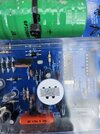
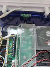
I've also installed a new delta bell - X and light box. The one on the front of the house was fully operational, but made it look quite unkept and out of date. It's a metal enclosure with a W on the clear PCB cover..... I'll post a photo just for nostalgia.... On the new delat bell x - I am still getting a tamper fault after completing install. Its not the front cover tamper switch. Is there a back tamper switch? It's raining now and I don't want to be climbing ladders until it's a little drier and I know what I am actually looking for!!
I assume this wiring diagram posted is correct? And the -12v needs the jumper onto one of the T terminals.. That's what I've done. I don't recall seeing the back tamper switch in the new delta x unit!!
Thanks so much...
Attachments
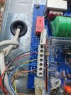
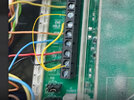
Have you put a wire link from 0v to one of the T terminals ?
Hi.
Yes. Did that from the -ve terminal to the bottom t terminal. Then t top terminal goes back to the t on the bell connections on the panel. edit. the bell tamper connection, specifically.Have you put a wire link from 0v to one of the T terminals ?
Last edited:
Just twist the blue and yellow at the kitchen pir and wire the hall with the blue and yellow i reckon that will work. Wrt the bell does it have the tamper switch with the circle base that goes at top left or is it the old style to the bottom left of the pcb ?
Yes, will do re blue and yellow wire, thanks. That was what I was going to do following your instructions.Just twist the blue and yellow at the kitchen pir and wire the hall with the blue and yellow i reckon that will work. Wrt the bell does it have the tamper switch with the circle base that goes at top left or is it the old style to the bottom left of the pcb ?
Yes, the delabellk x has the round tamper switch base top left, presses in and turns to lock into housing.
It is plugged in ?
Yes. The tamper switch. That stopped the alarm sounding as I had the cover open. But panel still says case tamper after exiting engineer menu. I'll take a photo of both ends of sub wiring and post . TksIt is plugged in ?
Case tamper ? …..it should say bell tamper
Right. Followed wiring instructions drawn with the 0v link and only 3 wires, using blue and yellow as one wire and twisted together at other pir location. That all seems to work now. Activated as intruder "06" in inputs and walk test completed. Previously it was set to "0" in settings. Fantastic, thank you.Yes, will do re blue and yellow wire, thanks. That was what I was going to do following your instructions.
Yes, the delabellk x has the round tamper switch base top left, presses in and turns to lock into housing.
Sorry. It says SAB tamper!Case tamper ? …..it should say bell tamper
On the SAB, I don't know what I could of done.
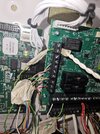
I'm getting some boots on and a ladder so I can take a photo. One thing I did do that was not required was run a +12v cable from alarm panel to b+. But I have now disconnected that this morning at alarm panel end!!!
Right. Followed wiring instructions drawn with the 0v link and only 3 wires, using blue and yellow as one wire and twisted together at other pir location. That all seems to work now. Activated as intruder "06" in inputs and walk test completed. Previously it was set to "0" in settings. Fantastic, thank you.Yes, will do re blue and yellow wire, thanks. That was what I was going to do following your instructions.
Yes, the delabellk x has the round tamper switch base top left, presses in and turns to lock into housing.
On the SAB, I don't know what I could of done.
Ok. Apologies, two issues were working against me. 1 I temporarily and loosly screwed on cover of deltabell x. And there were some spare wires stopping it from closing. So to rectify that I temp taped up the tamper switch. Still problem. Then I photographed both ends for learned advise on here, but when I looked at the photo of the bell wiring I could see my problem with the tamper jump wire. You don't see the alignment very well from beneath and only the photo solved it for me. Thanks so much....
will it work for engineer hold off in engineer menu with the C wire (green connected at panel end) and green to engineers hold off on bell? What output setting would I need to program? Or just forget....? Thanks again. Sorry for the distraction on this SAB tamper!
Edit. found this. Can try it.

 www.diynot.com
Not sure what endstation output means, can I choose any?
will it work for engineer hold off in engineer menu with the C wire (green connected at panel end) and green to engineers hold off on bell? What output setting would I need to program? Or just forget....? Thanks again. Sorry for the distraction on this SAB tamper!
Edit. found this. Can try it.
Pyronix Euro 46 engineer hold off on bell box
Hi I have euro 46 pyronix just installing another delta bell this has engineer hold off . It's wired in to the NC on the PGM and the C is on a 0v . So the question how do you program the control panel so in engineer menu you can open the tamper on the bell box ? Assum it's in outputs but not...
www.diynot.com
Not sure what endstation output means, can I choose any?
Attachments
DIYnot Local
Staff member
If you need to find a tradesperson to get your job done, please try our local search below, or if you are doing it yourself you can find suppliers local to you.
Select the supplier or trade you require, enter your location to begin your search.
Please select a service and enter a location to continue...
Are you a trade or supplier? You can create your listing free at DIYnot Local
Similar threads
- Replies
- 2
- Views
- 6K