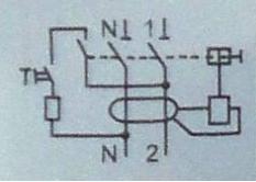
I have an RCD which is tripping, I could not find any issues with the circuits it feeds (I turned off the C/B's that it covers) I assumed!! it was the RCD playing up bought a new one and the L and N are swopped, old one L rhs and N lhs but the new one is opposite. Can anyone tell me it it is O.K. to use either way around as it is a breaker either it is on or off and the coil for tripping is monitoring imbalance across the two. I would just need to re' mark the front face of the trip with a new set of marks.
Thanks in advance Cambray
Thanks in advance Cambray