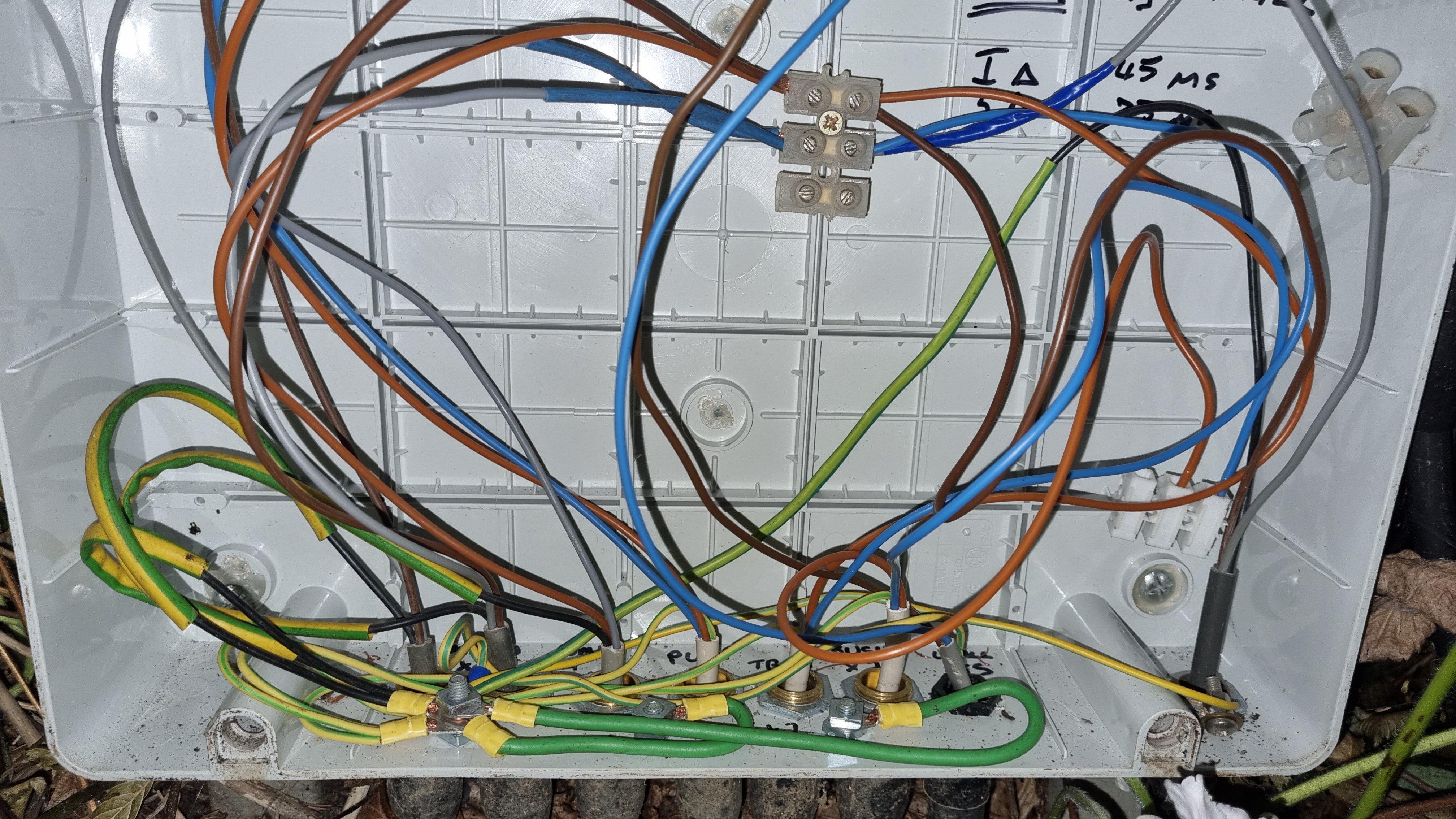
Well I'm confused.
Your drawing shows 8 cables in the main box, I see 7 - is that a me-issue? It is a bit scrappy but not unreasonable.
Currently I see cables linked as below:
View attachment 420655I believe I see:
an incoming switched feed connected to a PUMP circuit (C4) highlighted in green.
an incoming switched feed connected to a WALL LIGHTS (C5)circuit highlighted in blue.
a BUSH circuit connected to nothing highlighted in black.
a TREE circuit connected to a 'PUM' circuit highlighted in orange.
If this is the case only the wall lights and the pump can work.
I think you are saying you have been working on C1 which appears to be disconnected currently.
I see 3 blacks sleeved green/yellow and 4 cables containing green/yellow wires. All earth wires are linked
I see 3 greys sleeved blue.
Where is the 'missing circuit' (I assume the socket)?
You say this box is the original work and all the other pics are of extended work. Which circuits contain the grey earth/black neutral and where are the extensions terminated any chance of a pic of that junction box?
Have you verified there are no E-N or E-L faults and what test kit do you have?
Sorry lots of questions some of which I assume you have answered some but there's already a lot out there to absorb. This is a big system to faultfind on remotely and I'll not be surprised if it doesn't get resolved on here.
SUNRAY, thank you for getting into the detail of my garden electrics configuration. I agree, the circuit diagram has one more circuit than the photos are showing and I've now realised this is because the photos are a few years old and don't include the outdoor socket that was added in 2021. Here's a new photo I have just taken:
Here are the mappings of the circuits in my diagram to the garden wiring box.
In the garden wiring photo, as you say, there are 7 cables entering the box from the bottom, which are, from the left to the right:
a) From house switch 1 (pump on/off). SWA wires are coloured brown (L), black with earth sleave (E) and grey with blue sleave (N).
b) From house switch 2 (lights on/off). SWA wires are coloured brown (L), black with earth sleave (E) and grey with blue sleave (N).
the above are both labelled "MAIN X 2" in the box
c) PUMP LT- Circuit C2 - SWA wires are coloured brown (L), black with earth sleave (E) and grey with blue sleave (N).
d) PUMP - Circuit C4 - SWA wires are coloured orange (L), blue (N) and green/yellow (E).
e) TREE - Circuit C1 - SWA wires are coloured orange (L), blue (N) and green/yellow (E).
f) BUSH X 2 - Circuit C3 - SWA wires are coloured orange (L), blue (N) and green/yellow (E).
g) WALL LTS - Circuit C5 - cables wires are coloured brown (L), blue (N) and green/yellow (E).
h) Rightmost SWA cable - Circuit C6 (outdoor socket). SWA wires are coloured brown (L), black with earth sleave (E) and grey with blue tape (N).
As you say there are two incoming SWA cables at the left, labelled MAIN X 2. Both these cables come from a double switch in the house, so each cable is connected to one of the switches, allowing separate control of the garden water feature pump and all the garden lights.
The top (white) terminal connector shown in the wiring box are for the pump (C4) and the lower, slightly larger terminal connector is for all the lights except the festoon lights (C6), which are plugged into an outside socket fixed to the right side of the wiring box.
I apologise as the photo shows some of the lighting connections have been removed in order to test certain circuits. Normally all the lighting circuit cables would be connected to the live and neutral terminals in the centre of the wiring box. In the new photo I've just added, the BUSH x 2 (C3) and WALL LTS (C5) are currently disconnected.