Not sure. My point was that the maximum Zs is proportional to the voltage. So, with our meters, at least, calculating Zs from the actual voltage but we allowing only the 230V maximum then this will include some tolerance. Although the R1+R2 of the circuit in question will not alter, with a higher voltage a higher Zs would technically be allowed. So, we should use 230V for calculations or alter all of the parameters.
Exactly. If one calculated Zs using the actual voltage, if that voltage happened to be high at the time of measurement (e.g. 240V or 250V) and the Zs calculated on that basis was low enough for satisfactory ADS
at that voltage, if supply voltage were to fall (say to the nominal 230V, or even lower), PEFC may then become inadequate to satisfy ADS requirements. That is, I presume, why the regs plan to change the 'maximum Zs figures' to take into account the possibility that the supply voltage might be up to 6% below the nominal 230V.
That our meters determine Zs by dividing actual voltage (at the time) by actual current (at the time, at that voltage) is correct, and results in a true figure for the actual loop impedance, regardless of the voltage at the time. You would still get a correct figure for Zs even if (hypothetically) supply voltage were 100V or 500V at the time!
With a higher voltage and same R1+R2, PEFC will be higher causing the OPD to operate quicker and result in the CPC acceptability, or not, being unaffected.
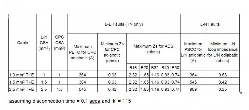
Are you now talking about my adiabatic calculations? If so,you are essentially right - but, as discussed, in practice we are not able to determine (from readily available data) the extent of that reduction in disconnection time - but, rather, are having to 'guess' a 0.1 sec figure.
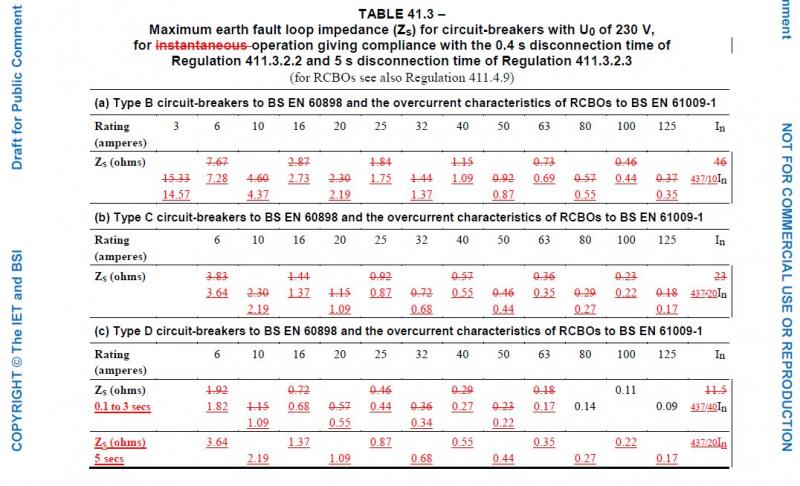
as you will be aware, the proposal for next year's Amd3 of BS7671 involves very extensive changes to all the 'maximum Zs' figures to take into account the fact that the actual supply voltage may be less than the nominal 230V
I was not aware. That doesn't seem logical.
See above - it seems pretty logical to me. As I understand it, they are seeking to ensure that the 'maximum Zs' figures they quote are low enough to result in satisfactory disconnection times even if supply voltage is only 230V-6%. Is that not logical?
Kind Regards, John


")