Relying on loads not being able to overload

I'm not really bothered what figure we have to use as maximum Zs. ... However, I am slightly irked by the methods being employed. ... Why are new tables not just issued which apply this new nominal voltage? ... Will there be ANY occasions when this new method will not be necessary? ... So, we look in the table at the maximum Zs for a device and reduce it to 76% of this so-called maximum which now can never be used.
I don't really understand your point. As I illustrated in an example Table from the DPC, the proposal IS to 'issue' (put into BS7671) new tables which indicate the maximum Zs that will (with the proposed new method of calculation) ensure compliant disconnection times. If/when those 'new tables' appear in BS7671, the OSG will presumably eventually follow with corresponding changes in its Tables.

I'm obviously missing your point, perhaps because I'm having a 'dumb morning' - what is it?

Kind Regards, John
 
Sponsored Links
I don't really understand your point. As I illustrated in an example Table from the DPC, the proposal IS to 'issue' (put into BS7671) new tables which indicate the maximum Zs that will (with the proposed new method of calculation) ensure compliant disconnection times. If/when those 'new tables' appear in BS7671, the OSG will presumably eventually follow with corresponding changes in its Tables.
Ah. Sorry.
I thought there was just going to be a correction factor (Cmin) which would always have to be applied.
 
I don't really understand your point. As I illustrated in an example Table from the DPC, the proposal IS to 'issue' (put into BS7671) new tables which indicate the maximum Zs that will (with the proposed new method of calculation) ensure compliant disconnection times. If/when those 'new tables' appear in BS7671, the OSG will presumably eventually follow with corresponding changes in its Tables.
Ah. Sorry. ... I thought there was just going to be a correction factor (Cmin) which would always have to be applied.
Oh, no - they propose to 'issue new tables'. If you recall:
The corresponding OSG Zs figures will, of course, (if/when changed) be lower than these by a factor of 1.24, since the OSG gives maximum Zs at 10°C, whereas BS7671 gives figures at 'normal operating temperature' (commonly 70°C).

Kind Regards, John
 
Moving back ‘on topic’, but taking on board the intervening discussion, it seemed appropriate to look at the impact of next year’s proposed changes to maximum permissible Zs values (for ADS) on the fault protection of conductors which are undersized’ (in relation to the In of the OPD protecting them). In the below, I have modified the maximum Zs figures to reflect the current proposal of ‘Cmin’=0.95 (i.e. calculating maximum Zs at a supply voltage of 218.5V). If the authors of BS7671 were to accept my suggestion that Cmin should really be 0.94 (i.e. calculating at 216.2V, the minimum permitted supply voltage), these Zs figures would reduce slightly.

It also occurs to me that if we are (I would say reasonably) moving to calculation of the maximum Zs which will still give adequate disconnection times at (or near!) the lowest permitted supply voltage, to be equally conservative (i.e. considering the ‘worst case’), I really ought to use the maximum permitted supply voltage (253V) to calculate the minimum Zs required to give adequate fault protection to the ‘undersized’ cable (per adiabatic calculation). I have therefore added such figures to my tabulation.
As can be seen, the combination of those two ‘conservative’ changes means that it is (just) effectively no longer possible for a 1mm² or 1.5mm² T+E cable to have adequate fault protection when protected by a B50 MCB, since the minimum Zs to achieve this for the CPC now coincides (at 0.70 Ω) with the maximum Zs for satisfying ADS requirements (disconnection times). Similarly, all the ‘Zs windows’ for an undersized’ cable having adequate fault protection get appreciably narrower - for example a 1mm² or 1.5mm² T+E cable protected by a B40 would have adequate fault protection if Zs were between 0.70Ω and 0.88Ω.

Kind Regards, John
 
Sponsored Links
Your calculations do not tell the whole story.

For example, using 0.1s as the time the Ia of the OPD could be used to calculate the minimum csa of the cpc.
For 50A MCB, 250A giving 0.69mm²
and 32A, 0.44mm².

A higher PEFC will reduce the time and, as I previously said, probably have no greater effect on the cpc - although 1mm² on a 50A MCB is stretching the exercise.

More accurate results should be obtained, if wanted, with more detailed calculations.
 
Your calculations do not tell the whole story. ... For example, using 0.1s as the time the Ia of the OPD could be used to calculate the minimum csa of the cpc. For 50A MCB, 250A giving 0.69mm² and 32A, 0.44mm².
Yes, just as with Ohms law, if you are given any two out of voltage, resistance and current, you can calculate the third, the same is true of the adiabatic calculation - given any two out of current, time and csa, one can calculate the third. Since I was interested in real-world cable sizes, I used csa and time to calculate currents. You have used current and time to calculate csa. The calculations we have done are entirely equivalent. If I had included a row in my table for a hypothetical cable with a 0.69mm² CPC, it would have shown that the maximum PEFC to satisfy the adiabatic calculation was 250A (and, similarly, 160A for a hypothetical 0.44mm² CPC).

So, in terms of what you've calculated, I agree with your calculations - i.e. the minimum csa which will 'tolerate' 250A for 0.1 sec is 0.69mm², and the minimum csa which will 'tolerate' 160A for 0.1 sec is 0.44mm². In the 'limiting case' you have considered (fault current exactly equal to Ia of the OPD), the minimum Zs (for adiabatic) and maximum Zs (for ADS) will be exactly the same if one calculates both Zs figures using the same voltage (say 230V).

However, if (as proposed) we reduced (to 218.5V or 216.2V) the voltage used for calculating maximum Zs, and even more so if (as I have suggested) we increased (say to 253V) the voltage used for calculating minimum Zs, then, in that 'limiting situation' the 'minimum Zs' would become greater than the 'maximum Zs' - meaning that it was impossible to simultaneously satisfy both the conductor protection and disconnection time requirements. In order to be able to satisfy both requirements, you would have to move away from your 'limiting situation' and calculate on the basis of a fault current greater than Ia of the OPD.
A higher PEFC will reduce the time and, as I previously said, probably have no greater effect on the cpc - although 1mm² on a 50A MCB is stretching the exercise. ... More accurate results should be obtained, if wanted, with more detailed calculations.
Yes, we've discussed this before, and have agreed that proper calculations require more information about OPD operating characteristics than we currently have - in particular an understanding of the relationship between fault current and disconnection time for currents greater than the Ia of the OPD. I have to say that the curve is 'so vertical' in that region that I suspect that accurate information may not be available (i.e. it may be very variable, due to 'chance' factors) - which is perhaps one reason why such information/data is not published.

Kind Regards, John
 
The IET said:
The committees are working on the comments, but I think yours is new, so I'll add it to the list. Thanks for sending it in.
I have to say that I'm very surprised - not so much because they are going to look at my late comment, but by the suggestion that my comment is 'new'. My comment that (in view of the ESQCR-permitted minimum supply voltage) I would have expected 'Cmin' to be be 0.94, rather than 0.95 seems so 'obvious' that I had imagined that many people would already have raised the same issue.
A follow-up message I've just received makes more sense, given the 'obviousness' of the matter I raised:
The IET said:
Looking at the comments I see that the 0.94 question has been raised by four other commenters, since yours was outside the time, I will not need to add it into the existing work of the panels - as they will examine 0.94 as a result of the other four. It would have been better if I had checked that earlier, sorry for any inconvenience due to that.

Kind Regards, John
 
Hello John,


Spent some time looking at this (please check all my calculations) and using books available to me:-

At 253V, for 70ºC sheathed cable the minimum Zs that can be tolerated at the MCB to provide protection to the CPC is 0.1 (V)/kS = 0.1(253)/115(1) = 0.22 ohms for 1mm² T/E.

I don't know where that would leave us with, say, a Ze of 0.20 ohms.

Regards
 
Hello John, ... At 253V, for 70ºC sheathed cable the minimum Zs that can be tolerated at the MCB to provide protection to the CPC is 0.1 (V)/kS = 0.1(253)/115(1) = 0.22 ohms for 1mm² T/E.
I think that should be sqrt(0.1) (V)/kS = (0.316)(253)/115(1) = 0.70Ω (per my tabulation above)

shouldn't it?

Kind Regards, John
 
John,

It may be, but I am basing my calculation on a formula and discussion in Electrical Installation Calculations (Coates and Jenkins) Fourth Edition - page 114 and 115.

Assuming that the definite minimum time is 0.01s , the minimum value of Zs at the MCB is given by:

0.1Uo/kS and goes on to say that at Uo=230V for 70ºC sheathed cable, then Minimum value of Zs at MCB = 0.200 ohms. There then follows some worked examples which uses this formula.

They have not shown the derivation of the formula but I see it as this:-

t=k²S²/I²

Substitute for I using V/R and knowing that the square root of 0.01 is 0.1 then you get the formula indicated.

Regards
 
John, It may be, but I am basing my calculation on a formula and discussion in Electrical Installation Calculations (Coates and Jenkins) Fourth Edition - page 114 and 115. ... Assuming that the definite minimum time is 0.01s , the minimum value of Zs at the MCB is given by: ....
Ah - so, yes, you're using the correct formula, but you are assuming a disconnection time of 0.01 second (hence, as you say, the square root of that is 0.1). I had thought that you were (like me) using a disconnection time of 0.1 sec, but had omitted to take the square root of it.

I have based all my calculations on a disconnection time of 
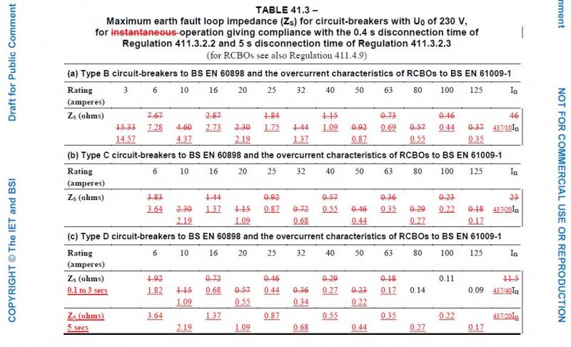
0.1 sec (of which the square root is, as I said, 0.316) - which seems to be the conservative figure which is usually used for such calculations. As we have discussed in this thread, there is a paucity of readily available details of precise disconnection times of MCBs. Whilst I agree that is quite possible that the disconnection time would be 0.01 secs (or maybe even lower), the standard published curves (e.g. those in BS7671) stop at 0.1 sec - which I presume is the reason why that is the figure commonly used for such calculations.

Whatever, what you seem to be overlooking is that (as is apparent from the fact that the calculated Zs is smaller with t=0.01 than with t=0.1) what you (and I) have calculated is the 
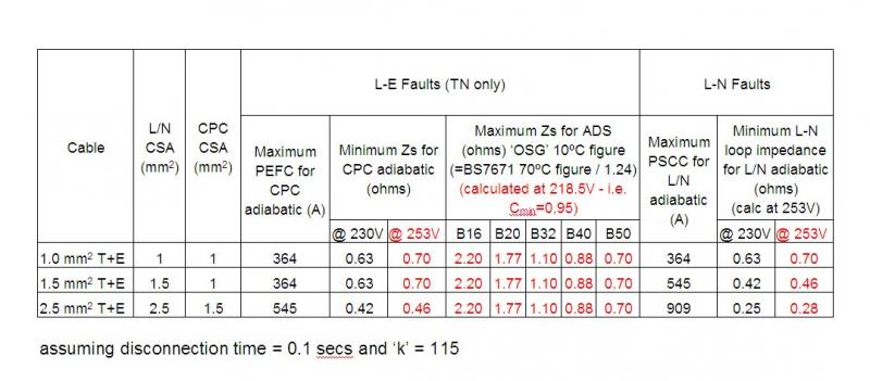
minimum Zs to ensure that the conductor had adequate protection. You asked what one would do if, with your calculated Zs of 0.22Ω, the Ze alone was 0.20Ω. However (contrary to what I think you were implying), given that your 0.22Ω is the minimum, from the point of view of conductor protection, any Zs greater than 0.22Ω (even much higher than 0.22Ω) would be fine. Of course, that's only half of the story. As well as this minimum Zs for conductor protection, there is also a maximum Zs that will achieve the required disconnection times. To satisfy both conductor protection and disconnection times, Zs has to between those minimum and maximum values (as illustrated in my tabulations above).

Kind Regards, John
 
That's it John.

My reasoning is that, if Coates and Jenkins have chosen 0.01 as the definitive minimum disconnection time, then why don't we? As you have implied, the choice of which disconnection time is used is seemingly arbitrary - from Appendix 3, why not 1 second or 10 seconds? So, I just thought that if more learned fellows had studied it and arrived at the 0.01 second as a basis for calculation of minimum Ze at the MCB, then that is perhaps what we should be using. This would provide for a much less restrictive range of Ze and R1+R2 combinations, highlighted by your table. I would like to understand from the powers that be which figure should be used.

The figure of 0.20 ohms was wrong, sorry. Please substitute 0.02 for 0.20. And I think this takes into the realms of having to consult manufacturers data for the particular MCB's concerned. The point being that this is another step that has to be undertaken/checked before the design process is complete.I have always understood that there is a maximum and minimum value.


Regards
 
That's it John. ... My reasoning is that, if Coates and Jenkins have chosen 0.01 as the definitive minimum disconnection time, then why don't we? ... This would provide for a much less restrictive range of Ze and R1+R2 combinations, highlighted by your table
I'm not sure I understand why you are interested in the 'definitive minimum disconnection time'. In terms of conductor protection, one surely should work with the 'worst case' scenario - i.e. the maximum possible, not minimum, disconnection time. If you calculate a minimum Zs on the basis of your 'minimum' disconnection time of 0.01 secs and had a Zs only just high enough in terms of that calculation, if the actual disconnection time proves to be greater than that 'minimum', then the conductor would not be adequately protected. One really must work with a disconnection time which one is certain will always be achieved - hence, I presume, the 'conservatism' of usual calculations.
I would like to understand from the powers that be which figure should be used.
As above, one really needs to work with a disconnection time that one is certain will always be achieved. If better data than we usually see (I would imagine from the manufacturers of MCBs, rather than 'the powers that be') is available, then that would obviously be valuable. However, as I wrote earlier in this thread, I suspect that there may be a good reason why this data is not 'readily' (if at all) available - namely that I can well imagine that once when gets down to disconnection times appreciably less than 0.1 secs, MCB performance becomes increasingly more variable/unpredictable (due to a host of factors), such that one could not reliably guarantee what the disconnection times would be. If that's true, it would be another explanation of why we usually use the 'conservative' 0.1 sec figure. I would think that it would take very little in the way of 'factors' to turn a 10 msec disconnection time into, say, a 15 or 20 msec one.
The figure of 0.20 ohms was wrong, sorry. Please substitute 0.02 for 0.20. And I think this takes into the realms of having to consult manufacturers data for the particular MCB's concerned.
As above, although I may be wrong, I'm not convinced that even the manufacturers could necessarily provide reliable data much below 0.1 sec - not because they haven't looked into it, but because MCB behaviour becomes far more variable ('unpredictable') at very short disconnection times.

Kind Regards, John
 
This is merely an exercise for the hypothesis posed in this thread.

In practice it doesn't matter what the minimum or maximum Zs is but whether the cpc is of sufficient csa to withstand the fault current resulting from the actual or designed Zs.

434.5.2
 
This is merely an exercise for the hypothesis posed in this thread. ... In practice it doesn't matter what the minimum or maximum Zs is but whether the cpc is of sufficient csa to withstand the fault current resulting from the actual or designed Zs. ... 434.5.2
... but you've just said the same thing in a different way! The cpc will be "of sufficient csa to withstand the fault current" if the actual Zs is above the 'minimum Zs' figure (for that csa) calculated in the manner discussed above.

The 'maximum Zs' of the circuit is obviously a different (and more familiar) matter and, as we all know, is the Zs above which required disconnection times will not be achieved in response to a fault of negligible impedance (regardless of the cable csa which results in the prevailing Zs).

Kind Regards, John
 

DIYnot Local

Staff member

If you need to find a tradesperson to get your job done, please try our local search below, or if you are doing it yourself you can find suppliers local to you.

Select the supplier or trade you require, enter your location to begin your search.


Are you a trade or supplier? You can create your listing free at DIYnot Local

 
Sponsored Links
Back
Top