Relying on loads not being able to overload

Yes, I realise that but it's not done that way round.

Also, using either 0.1s with the actual fault current or 0.01s with any fault current is not accurate.
 
Sponsored Links
Yes, I realise that but it's not done that way round.
Sure, but when one is talking in general (without knowing the actual Zs) one really has to do it 'that way around'.
Also, using either 0.1s with the actual fault current or 0.01s with any fault current is not accurate.
We are all agreed that we don't have enough detailed information about the operating characteristics of MCBs (although I am doubtful whether reliable data of the type we'd like to have necessarily exists).

However, I doubt that the actual fault current is all that relevant, since it's clear that the curve is virtually 'vertical' in the region which interests us. The question really relates to how far below 0.1 sec the curve goes before 'stopping' - it clearly has to 'stop' somewhere since there is bound to be an 'absolute minimum' time it will take the mechanism to operate, no matter how high the current.

Kind Regards, John
 
Much more experienced people than me have stated that the design step uses the formula 0.1 Uo/kS - to determine minimum Ze at the MCB - that is Coates and Jenkins. Surely we should try to understand why they say that? Unless I have misinterpreted/misapplied?

Regards
 
Sponsored Links
Much more experienced people than me have stated that the design step uses the formula 0.1 Uo/kS - to determine minimum Ze at the MCB - that is Coates and Jenkins. Surely we should try to understand why they say that? Unless I have misinterpreted/ misapplied?
I fully understand your point and I, too, would like to understand how/why (on the basis of what you're telling me) they seemingly base their calculations on an assumed disconnection time of 0.01 sec.

FWIW, The IET's "Electrical Installation Design Guide: calculations for electricians and designers" appears to consistently use a disconnection time of 0.1 sec for such calculations [which changes the above formula to 0.316 Uo/kS]. Whether that means that Coates and Jenkins know something which the IET doesn't know, I couldn't say.

Kind Regards, John
 
Much more experienced people than me have stated that the design step uses the formula 0.1 Uo/kS - to determine minimum Ze at the MCB - that is Coates and Jenkins. Surely we should try to understand why they say that?
Further to my recent response, I think I may have discovered why the 'general practice', which most of us follow, does not assume a disconnection time of 0.01 secs (and probably why we usually use 0.1 secs).

I recently wrote to EFLI that MCB operating curves are essentially vertical '...in the region which interests us'. What I should have said is '... over disconnection times from well over 1 second down to 0.01 seconds' (0.1 seconds being where the BS7671 curves stop). However, I've now found a curve in the IET Elecrical Installation Design Guide which gives (unfortunately only for a Type D MCB) some insight into what happens to the curve below 0.1 seconds....
As can be seen, the curves remain 'straight and virtually vertical' down to about 0.05 sec but, below that, things change dramatically. If you consider the D10 curve above (the easiest to see!), the curve is, as expected, 'straight and virtually vertical', at a current of 200A (20 x In) from about 3 seconds down to about 0.05 seconds. However, since the curve then deviates from its previous straight line, to get down to 0.01 secs requires a current of about 500A (50 x In). Although much more difficult to see on the curves, for a D32, the curve is 'vertical' at a current of 640A down to about 0.05 secs, but to get down to 0.01 secs requires a current of around 1600A.

I obviously don't know whether Type B and C MCBs behave in the same fashion, but I suspect they are probably similar. If that is the case, then to use 0.01 sec would only be appropriate if one knew that PFC was more than about 2.5 times the 'magnetically operating' current (i.e. that Zs was less than about 40% of what would be needed to just satisfy disconnection time requirements). The curves above suggest that it would probably be reasonable to assume 0.05 secs (rather than 0.1 sec) for a Type D. However, maybe the curves are not 'vertical and straight' down as low as 0.05 secs for Type B and C MCBs - which could well explain the generic 0.1 sec which seems to be assumed in calculations (by most people!) for any type of MCB.

Of course, if (at least for a Type D) one knows that the PFC is at least 2.5 times the 'magnetic trip' current (which obviously implies a Zs which is 2.5 less that that which would be necessary to satisfy disconnection time requirements), then one could legitimately use 0.01 secs for adiabatic calculations.

What we now need is to see some of these 'below 0.1 sec curves' for Type Bs and Cs!

Kind Regards, John
 
Have done some googling - the nearest I can find is that 0.01 seconds represents one half cycle of sine wave mains - below that (and above 5 seconds) the equation becomes non-adiabatic and energy let through calculations are considered more appropriate.

Understanding that using the 0.1 sec provides for a 'safer' assessment of Ze min - would it not also imply that many existing circuits are not safe? So, say a measured Ze of 0.15 ohms and a 5m run of 2.5/1.5 at operating temperature of 70ºC giving a calculated R1+R2 of approx 0.11 ohms - therefore a Zs of 0.26 ohms - are we saying that this circuit is unsafe?

An expert in the other place advises using the maximum time - others different times - all in all it seems arbitrary and so am going to try and seek clarification at the other place.


Regards
 
Have done some googling - the nearest I can find is that 0.01 seconds represents one half cycle of sine wave mains ....
Yes, I almost mentioned that last night. One thing is fairly clear. Although I realise it has not been suggested, to assume any disconnection time less than 0.01 seconds for these simple calculations would almost certainly not be safe. If one gets down to less that half a cycle, behaviour is bound to be at least somewhat unpredictable, since it becomes dependent on the point in the cycle at which the fault arises - if current flows for less than a half cycle, there is no guarantee that the potential peak current (of the whole wave) will ever flow.
... below that (and above 5 seconds) the equation becomes non-adiabatic and energy let through calculations are considered more appropriate.
Sure. Above about 5 seconds, the whole process becomes non-adiabatic (i.e. there is time for some thermal movement to occur), so the whole adiabatic approach becomes inappropriate, and much more complex calculations would be required. If current flows for very short periods (e.g. <0.01 seconds), the process is very much adiabatic. However, if one gets down to less than half a cycle, the simplistic adiabatic equation as given in 543.1.3 can no longer be used, since the square of the RMS current multiplied by time no longer represents the ‘let through energy’. The same theoretically also applies whenever ‘t’ is not an exact number of half cycles, but the consequences of that are trivial if ‘t’ is at least a few cycles in length.
Understanding that using the 0.1 sec provides for a 'safer' assessment of Ze min - would it not also imply that many existing circuits are not safe? So, say a measured Ze of 0.15 ohms and a 5m run of 2.5/1.5 at operating temperature of 70ºC giving a calculated R1+R2 of approx 0.11 ohms - therefore a Zs of 0.26 ohms - are we saying that this circuit is unsafe?
I would say that answering that question requires two additional bits of information - firstly, as discussed, a proper understanding of how the t/I relationship of a MCB behaves at disconnection times below 0.1 sec and, secondly, knowledge of the In of the MCB protecting the circuit. If calculated conventionally using 230V, your Zs of 0.26&#937; corresponds to a PFC of 884A. 
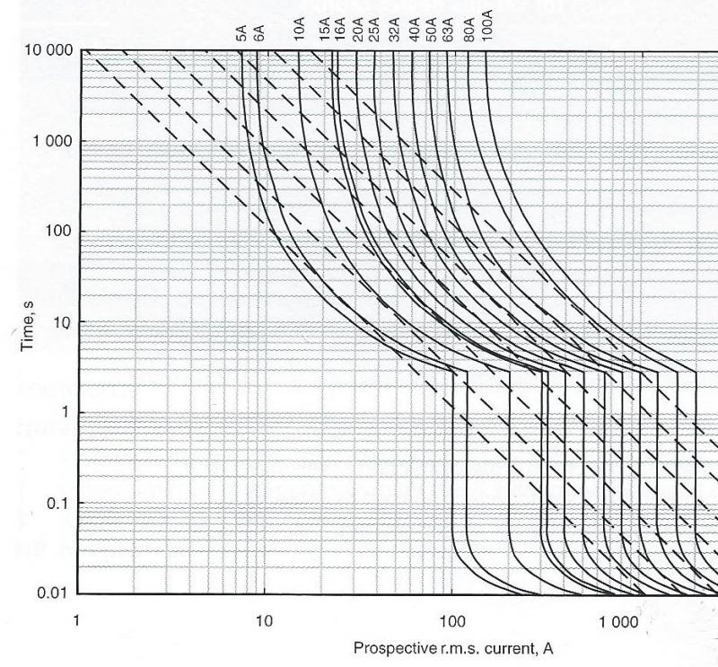
IF the curve for a Type B MCB is similar to the Type D curves I posted last night, then that PFC would be enough to achieve a disconnection time of 0.01 seconds (or less) for any Type B MCB with an In up to around 70A - in other words, any domestic Type B would achieve a disconnection time of 0.01 seconds (or less). One would therefore be justified in using t=0.01 for the adiabatic calculation, which would result (assuming 253V) in a ‘minimum Zs’ of about 0.15 &#937;. So, if the above assumption about the t/I curve is correct then the circuit you describe would be ‘safe’ for any MCB with an In less than about 70 A. However, I can only say that because I have looked at curves not readily available to most electricians (and assumed Type B ones are similar!) - it is not true that a calculation undertaking assuming a 0.01 second disconnection time will necessarily give a correct answer asti whether or not the conductor is 'safe' for any circuit.
An expert in the other place advises using the maximum time - others different times - all in all it seems arbitrary and so am going to try and seek clarification at the other place.
It’s probably not so much arbitrary as ‘simplified and conservative’, particularly given that most electricians do not have easy access to t/I curves for MCBs which go below 0.1 seconds. If the Zs were such that PFC were much closer to the ‘magnetic trip current’ (e.g. 5*In for a Type B) than in your example then, if those Type D curves I posted last night are typical of all MCBs, the disconnection time could be appreciably above 0.01 secs (although, I agree, not as high as 0,1 seconds). Given the wide spectrum of knowledge, abilities and resources of electricians, it probably does make sense to suggest, as a ‘guideline’, calculations on the basis of an assumed disconnection time appreciably greater than 0.01 seconds, although perhaps not as high as 0.1 seconds. Those with adequate knowledge, skills and access to the relevant data can always undertake ‘proper’ calculations, as per those above.

Don’t forget that, for those unable or uninclined to undertake adiabatic calculations, the regs offer a ‘deemed to satisfy’ option in the form of Table 54.7, which is extremely conservative - requiring a CPC csa equal to the csa of the line conductor (up to 16mm²).

Having said all that, I would certainly be interested to hear whatever other opinions you can obtain.

Kind Regards, John
 
Page 3.36 Fig.6
http://www.neweysonline.co.uk/neweys/pdf/Hager_Protection_Devices_Technical.pdf
Doesn't this show what I said is correct in that if the use of Ia and 0.1s shows the cpc to be adequate then it will also be satisfactory at higher currents because currents above Ia cause proportionately greater increases in the speed of disconnection (within usual peramaters).
That is not necessarily true - it depends crucially upon the actual shape of the t/I curve in the region when currents exceed the minimum required to achieve a magnetic trip. The required CPC depends upon I²t. If, for example, you double the current, the required csa will actually increase unless the effect of that increase in current is to reduce the disconnection time by a factor of at least 4 - which I actually doubt is the case with the curves we are looking at. To illustrate, an example ...

start with I = 300, t=0.1, k = 115
minimum csa = sqrt(300² * 0.1)/115 = 0.825 mm²

increase I to 600 (2 times). If this resulted in t reducing to exactly 0.025 (4 times less),then
minimum csa = sqrt(600² * 0.025)/115 = 0.825 mm²
...i.e., as expected, exactly the same.

However, if the doubling of current only resulted in, say, a halving of disconnection time (to 0.05 secs) then:
minimum csa = sqrt(600² * 0.05)/115 = 1.17 mm²
... an appreciably higher csa requirement!

So, whether what you say is correct depends crucially on the nature of the t/I relationship (i.e. the shape of t/I curve). I may be wrong but, as I said above, I somewhat doubt that t is inversely proportional to I². If the effect of I on t is less ‘violent’ than that, then increasing current would result in an increase in required CPC csa.

Kind Regards, John
 
start with I = 300, t=0.1, k = 115
minimum csa = sqrt(300² * 0.1)/115 = 0.825 mm²
Sorry, where does 300 come from?


Did you not look at the graphs to which I linked.

It would appear that B, C, and D are the same for Ia.

It would seem that for B Ia (5In) the time is 0.02s and for 6In (+ 20%) the time is 0.01s ( - 50%).
Above 6In it seems to be still 0.01s.

I did say with the usual parameters so it would seem that 0.01s can be used for currents greater than 6In.


So, for a Zs of 0.2&#937; (1150A) the csa has to be a minimum of 1mm².
1150A / 6 = 191A, therefore all usual MCBs are very adequately covered.

Therefore my supposition that a csa being satisfactory by using Ia and 0.1s is very conservative and only if not are more accurate calculations required.
 
Not ignoring you EFLI - all points noted.

John, do not quite understand - you have put forward a table which states that the minimum Zs for a 2.5mm/1.5mm cable is 0.46 ohms at 230V. I have put forward an example where Zs = 0.26 ohms and asked whether this is safe. You then argue that you need two further pieces of information to assess whether this is safe. So, if Zs=0.26 ohms, are you saying that the figures in your table are incorrect, not sure or waiting for further details?

I am going to go away now fearing that we may be entering a circular discussion but will come back if/when I find anything more concrete to add.

Regards
 
start with I = 300, t=0.1, k = 115
minimum csa = sqrt(300² * 0.1)/115 = 0.825 mm²
Sorry, where does 300 come from?
Oh, I'm sorry, too! It was just an arbitrary round number used for convenience for the purpose of illustration - you could substitute any other current you like (and then double that current in the two subsequent calculations.
Did you not look at the graphs to which I linked. It would appear that B, C, and D are the same for Ia ... It would seem that for B Ia (5In) the time is 0.02s and for 6In (+ 20%) the time is 0.01s ( - 50%). ... Above 6In it seems to be still 0.01s. ... I did say with the usual parameters so it would seem that 0.01s can be used for currents greater than 6In.
Yes, I did look at the graphs, but seemingly not carefully enough, since I didn’t notice/realise that they are very different from the one I posted last night. Also, in terms of the calculations I recently presented, the Hager curves indicate that a 20% increase in current ( from 5*In to 6*In) results in a disproportionately large (50%) decrease in disconnection time, much more change than I had expected.

Of course, the situation is a bit complicated by the ‘spread’ of operating characteristics (as illustrated in your graphs) which is permitted by the Standards. Whilst one MCB might not achieve 0.02s until 5*In, another might achieve 0.01s at about 3.5*In. However, I agree that, on the basis of those curves, the ‘worst case’ appears to be that one achieves 0.01s with about 6*In. I am, however, more than a little concerned that this differs so much from the curves in the IET Guide (which I posted last night), which seemed to suggest that (by extrapolation from a D10), one would need about 12.5*In to get 0.01 sec with a Type B MCB, and also indicate that disconnection time is about 0.05s (rather than 0.02s per Hager) with a current of 5*In.

The fact that the Hager curves flatten out at 0.01s, regardless of how high the current gets may reflect the fact that this is around the shortest time in which the mechanism can physically operate and/or the fact (as recently discussed) once one gets down to less than a half-cycle, things become much less predictable due to the dependence on the part of the cycle at which the fault arises.

So, for a Zs of 0.2&#937; (1150A) the csa has to be a minimum of 1mm². 1150A / 6 = 191A, therefore all usual MCBs are very adequately covered.
I can’t disagree with that, provided those Hager curves (which, as I said, are very different from the one in the IET Design Guide) are correct and generally applicable. So I suppose I am essentially ‘conceding’. I suppose the fact that I can now do that is not actually inconsistent with what I have been saying all along - that if we had decent data on how MCBs behave below 0.1s, we would be able to work out the true answer.

Having said that, you can probably understand that I’m still unconvinced that we do have ‘decent data’ about the curves, given the dramatic difference between Hager’s ones and those in the IET Design Guide - so maybe the jury is still at least partially out!

Mind you, even if one assumes that the Hager curves are the correct ones, the steepness of the curve between 5*In and 6*In means that it is a pretty critical/‘fragile’ situation - i.e. small changes in Zs (hence PFC) result in large changes in disconnection time. For that reason, and assuming we accept the Hager curves, I think I would probably be inclined to use 0.02s, rather than 0.01s, unless I was sure that PFC was well above 6*In.

Kind Regards, John
 
Trying to calculate the let through energy of a circuit breaker operating on a magnetic trip using the fault level and your assumed disconnection time (the regs assume 0.1 sec but it might in practice be 0.01 or 0.03 or 0.04 etc) is likely to lead to nowhere, most modern devices have some degree of energy limiting too.

What you need to do is consult either the manufacturers data if available or the generic I²t data in BSEN60898 which will give you the I²t at various fault levels.

When you have the I²t for the CPD you can then compare with the K²S² of the cable, if the former is smaller than the later than all is well, if its larger then you have a design issue. This is the re-arrangement of the adiabatic that I find easiest to use

Remember that you must consider the most onerous condition, so obtain I²t for a fault occurring at the board and at furthest point. You'll find though that for a magnetic device (where t is *roughly* constant) that the worst case is where the fault current is highest as long as at the far end the fault current is still sufficient to operate magnetic trip (ie. zs within tablulated values) For a thermal device, (such as a fuse) the worst case is far end as the I²t to blow it (remember this is directly proportional to enegry) remains more or less constant, however at lower currents some of it transfers into the environment (think of a 240v kettle on 110v, it'll still put thermal energy into the water but it probably wont ever boil even after an hour).

Circuit breakers also have a thermal element as well to confuse matters, the zs might be too high to trip your D63 on the magnetic trip, but if you get the curves out the back of the regs you might find that you acheieve disconnection in 3.2 seconds for example, you would then have to calculate the I²t yourself. This would be usual on a modern install, but say you have a dorman smith loadmaster 30A type 4 breaker on a ring circuit, these had a max zs for 0.4 seconds of 0.66 ohms, but if you looked at the data you would find that this is relying on the thermal element, to hit the magnetic trip you would need a zs of less than about 0.32 ohms. So lets say you had a zs of 0.66 (lets forget for now about 80% ROT). That would actually take 0.4s to disconnect with current of 360A thats an I²t of 51840. So your K²S² needs to be above this, so with a K=115, S needs to be at least 1.97mm². So clearly a problem if installed with 2.5/1.5 cable, and these breakers were around at the time of 2.5/1.0mm cable. They are actually worse than a a re-wireable fuse!
 
John, do not quite understand - you have put forward a table which states that the minimum Zs for a 2.5mm/1.5mm cable is 0.46 ohms at 230V. I have put forward an example where Zs = 0.26 ohms and asked whether this is safe. You then argue that you need two further pieces of information to assess whether this is safe. So, if Zs=0.26 ohms, are you saying that the figures in your table are incorrect, not sure or waiting for further details?
That's simple enough to answer. In terms of 'my table' which, as I indicated when I presented it, assumed a disconnection time of 0.1s, as you say, a Zs of 0.26 would clearly not be 'safe'.

However, you introduced the suggestion that we should calculate on the basis of a shorter disconnection time, and I said that, in order to decide whether that would be possible (in which case the calculation might well show the circuit to be 'safe'), one would need to know those those two extra things - in order to determine whether use of a shorter (than 0.1s) disconnection time could be justified.
I am going to go away now fearing that we may be entering a circular discussion but will come back if/when I find anything more concrete to add.
Fair enough. I look forward to hearing anything useful you discover. I would be particularly interested to see any other t/I curves for MCBs you may come across since, given the pretty dramatic difference between Hager's and the IET's, we really need a 'decider' or three!

As you will have seen, I have conceded that, if one accepts Hager's curves as being the correct ones, it would seem reasonable to undertake adiabatic calculations on the basis of of 0.02s disconnection time, and probably 0.01 sec if PFC was well over 6*In (for a Type B).

Kind Regards, John
 

DIYnot Local

Staff member

If you need to find a tradesperson to get your job done, please try our local search below, or if you are doing it yourself you can find suppliers local to you.

Select the supplier or trade you require, enter your location to begin your search.


Are you a trade or supplier? You can create your listing free at DIYnot Local

 
Sponsored Links
Back
Top