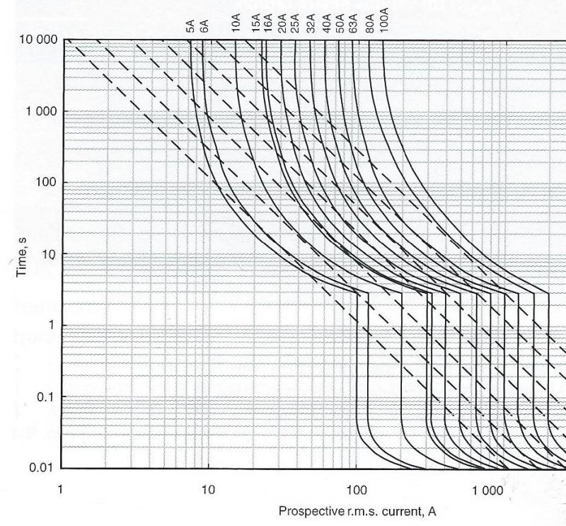
Have done some googling - the nearest I can find is that 0.01 seconds represents one half cycle of sine wave mains ....
Yes, I almost mentioned that last night. One thing is fairly clear. Although I realise it has not been suggested, to assume any disconnection time
less than 0.01 seconds for these simple calculations would almost certainly not be safe. If one gets down to less that half a cycle, behaviour is bound to be at least somewhat unpredictable, since it becomes dependent on the point in the cycle at which the fault arises - if current flows for less than a half cycle, there is no guarantee that the potential peak current (of the whole wave) will ever flow.
... below that (and above 5 seconds) the equation becomes non-adiabatic and energy let through calculations are considered more appropriate.
Sure. Above about 5 seconds, the whole process becomes non-adiabatic (i.e. there is time for some thermal movement to occur), so the whole adiabatic approach becomes inappropriate, and much more complex calculations would be required. If current flows for very short periods (e.g. <0.01 seconds), the process is very much adiabatic. However, if one gets down to less than half a cycle, the simplistic adiabatic equation as given in 543.1.3 can no longer be used, since the square of the RMS current multiplied by time no longer represents the ‘let through energy’. The same theoretically also applies whenever ‘t’ is not an exact number of half cycles, but the consequences of that are trivial if ‘t’ is at least a few cycles in length.
Understanding that using the 0.1 sec provides for a 'safer' assessment of Ze min - would it not also imply that many existing circuits are not safe? So, say a measured Ze of 0.15 ohms and a 5m run of 2.5/1.5 at operating temperature of 70ºC giving a calculated R1+R2 of approx 0.11 ohms - therefore a Zs of 0.26 ohms - are we saying that this circuit is unsafe?
I would say that answering that question requires two additional bits of information - firstly, as discussed, a proper understanding of how the t/I relationship of a MCB behaves at disconnection times below 0.1 sec and, secondly, knowledge of the In of the MCB protecting the circuit. If calculated conventionally using 230V, your Zs of 0.26Ω corresponds to a PFC of 884A.
IF the curve for a Type B MCB is similar to the Type D curves I posted last night, then that PFC would be enough to achieve a disconnection time of 0.01 seconds (or less) for any Type B MCB with an In up to around 70A - in other words, any domestic Type B would achieve a disconnection time of 0.01 seconds (or less). One would therefore be justified in using t=0.01 for the adiabatic calculation, which would result (assuming 253V) in a ‘minimum Zs’ of about 0.15 Ω. So, if the above assumption about the t/I curve is correct then the circuit you describe would be ‘safe’ for any MCB with an In less than about 70 A. However, I can only say that because I have looked at curves not readily available to most electricians (and assumed Type B ones are similar!) - it is not true that a calculation undertaking assuming a 0.01 second disconnection time will necessarily give a correct answer asti whether or not the conductor is 'safe' for
any circuit.
An expert in the other place advises using the maximum time - others different times - all in all it seems arbitrary and so am going to try and seek clarification at the other place.
It’s probably not so much arbitrary as ‘simplified and conservative’, particularly given that most electricians do not have easy access to t/I curves for MCBs which go below 0.1 seconds. If the Zs were such that PFC were much closer to the ‘magnetic trip current’ (e.g. 5*In for a Type B) than in your example then, if those Type D curves I posted last night are typical of all MCBs, the disconnection time could be appreciably above 0.01 secs (although, I agree, not as high as 0,1 seconds). Given the wide spectrum of knowledge, abilities and resources of electricians, it probably does make sense to suggest, as a ‘guideline’, calculations on the basis of an assumed disconnection time appreciably greater than 0.01 seconds, although perhaps not as high as 0.1 seconds. Those with adequate knowledge, skills and access to the relevant data can always undertake ‘proper’ calculations, as per those above.
Don’t forget that, for those unable or uninclined to undertake adiabatic calculations, the regs offer a ‘deemed to satisfy’ option in the form of Table 54.7, which is extremely conservative - requiring a CPC csa equal to the csa of the line conductor (up to 16mm²).
Having said all that, I would certainly be interested to hear whatever other opinions you can obtain.
Kind Regards, John


