

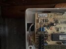
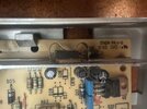
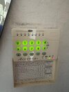
I am trying to help my elderly neighbour make good his old alarm system whilst doing some work on our semi detached houses. The system appears to be a Honeywell Accenta variation - quite odd, as the case appears to be from a Challenger G4 (outside label just has "Challenger" on it), but the board inside is very much a Honeywell Accenta G3 from what i've found out - bit of a frankenstein as the RKP seems to be from an Accenta G4 (He did say someone replaced the faulty keypad for him some time ago).
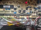
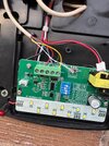
The outside bell box was the 30-40 year old large rectangular variety, with a basic siren and a strobe connected directly to the BELL+/- and STROBE+/- at the control panel (as the attached photos show). Thinking this was a Challenger controller, I purchased a Challenger AU1000WBX universal bell box and sounder, but that obviously didn't work as the power through the BELL+/- or STROBE +/- is disabled when the alarm is disarmed, meaning the device constantly goes through the delay startup sequence at every activation!
After some research (read google and engineer manuals!) I moved the Bell +/- to the 13v output +/- terminals, and connected one of the other 2 wires to BELL- and the other to STROBE-, connecting them to 12v +/- in the bell box, and to Trig- and STRB- respectively. Alarm box now arms and stays on after a code is entered, but after the 2 minute delay the siren goes off and (but not strobe oddly) - alarm panel shows everything normal and disarmed. From what i can gather and measure with a multimeter, when the alarm is armed and going off, the output from the Bell/STROBE- controller terminals tie down to 0v so i get full voltage between the 13v output+ and the - terminals for the BELL/STROBE; as soon as it's disarmed, this voltage drops to 0v, i assume because it then floats?
I can't see any way to program or change a jumper or wiring in this old unit so the trigger 0v is inverted and i don't think this alarm has a programmable option to change it. My neighbour can't afford to replace it (he's 85) so i want to try and get this working for him if i can.
Is there any way to change the trigger behaviour on the controller so it responds the way the AU1000WBX is expecting? it was suggested to force it high by adding a 47K resistor between +/- terminals of BELL and STROBE so it might behave in a way the bell box expects, but not sure if thats the right approach - can anyone please help?
Thank You!
Attachments
-
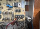 WhatsApp Image 2026-09-28 at 22.16.42 (1).jpeg220.1 KB · Views: 3
-
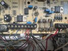 WhatsApp Image 2026-09-28 at 22.16.42 (2).jpeg261 KB · Views: 2
-
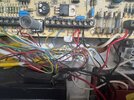 WhatsApp Image 2026-09-28 at 22.16.42 (3).jpeg277.5 KB · Views: 2
-
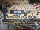 WhatsApp Image 2026-09-28 at 22.16.42 (6).jpeg285.5 KB · Views: 2
-
 WhatsApp Image 2026-09-28 at 22.16.42 (7).jpeg125.7 KB · Views: 2
-
 WhatsApp Image 2026-09-28 at 22.16.42 (9).jpeg165.1 KB · Views: 2
-
 WhatsApp Image 2026-09-28 at 22.16.42 (13).jpeg298.2 KB · Views: 2
-
 WhatsApp Image 2026-09-28 at 22.16.42 (14).jpeg144.1 KB · Views: 2
-
 WhatsApp Image 2026-09-28 at 22.16.42 (15).jpeg165.6 KB · Views: 2
-
 Challenger AU1000WBX.jpeg326.4 KB · Views: 2
