• Looking for a smarter way to manage your heating this winter? We’ve been testing the new Aqara Radiator Thermostat W600 to see how quiet, accurate and easy it is to use around the home. Click here read our review.

Replacing old Horstmann 423 with RWB30E

Joined
9 May 2004
Messages
75
Reaction score
0
Location
England
Country
United Kingdom
Hello,
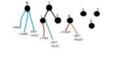
Please see the attached image im looking at replacing the Horstmann 423 timer with a Siemens RWB30E. As you can see on the pic there is the timer and a temp control, now we are sure that this temp control has never worked right for many years and does nothing, so in theory it is not required.

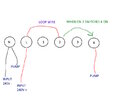
I work with electronics so feel confident doing this, but need to be sure first. Looking at the RWB30E I assume that N goes to neutral from fused spur and L goes to live from fused spur, assuming I dont want to connect the Satchwell temp device as I don't believe this works anyway, that only leaves the grey cable which goes to the boiler pump (its at 1970s non combi boiler and hot water is fed via rad's and switch on immersion heater) I not yet checked but I think the grey cable to pump is 2 wire, so does that go to 2 and 4 on the RWB30E ? The image also shows a "link" between L and 2 and N and 4 so is any form of link wire required ? Thanks.
Capture1.JPG
rwb.JPG
 
Sponsored Links
The temp control you refer to is a frost thermostat, it would override the timeswitch and turn the heating on when the temperature drops low enough to pose a risk of pipes freezing. They are normally be set at around 5C, and are usually installed in places such as an unheated garage, outhouse or cellar etc., where frost protection is required. The thermostat would then start the boiler when the temperature drops to 5C, even when the timeswitch was off.

The two timeswitches you refer to are both simply an on/off switch with a mains supply to provide them with operating power, so a direct exchange is usually straight forward as you are swapping devices that have an identical functionality.

From the info I have, the electrical terminals for the existing timeswitch should be:

423.jpg


The mains supply is obvious L&N for the 423 and the same for the RWB30E.

From the 423 diagram above, if yours is the same, the 'switching' terminals are 3 and 4, which would correspond with 2 and 4 on the RWB30E so the existing wires would transfer across accordingly.

423 terminal 3 = RWB30E terminal 2
423 terminal 4 = RWB30E terminal 4

There is a link between terminals L and 3 shown in the 423 diagram above, and if it's present, then the RWB30E will need a corresponding link (shown in dotted in the diagram in your photo) between L and 2.

As you don't mention any other controls room thermostat, hot water cylinder thermostat, motorised valve(s) etc. I assume this is an ancient system where other than the froststat the timeswitch is the only control.

 
Hi @stem thank you for the detailed reply. Yes this is a very very old system and time switch is only control for heating.

Ah yes the frost thermostat that makes sense, well this is all in the kitchen, so I guess I could just add it back in using same connections just in case.

I not yet looked inside the 423 so not sure how its wired, but if there is a link installed then I will install a link wire between L and 2 on the RWB30E as you stated.
 
Hello @stem (or anyone who knows please) I would just like to confirm something as I checked current wiring

N = Neutral from power & neutral to pump & Blue to frost protect (but this frost protect is not been connected on new timer)
L = Live from power & Green to frost protect & connected by loop to 1 and 3
1 & 3 & L = Connected via loop together
4 = live to pump & brown to frost protect
2 & 5 & 6 = nothing connected.

So based on the above I am not sure where to put a loop wire on the new RWB30 ?
Ive attached an image of original wiring
 

Attachments

  • boiler timer original wirng.jpg
    boiler timer original wirng.jpg
    37.6 KB · Views: 8
Last edited:
So based on the above I am not sure where to put a loop wire on the new RWB30 ?
Ive attached an image of original wiring
There is a link between terminals L and 3 shown in the 423 diagram above, and if it's present, then the RWB30E will need a corresponding link (shown in dotted in the diagram in your photo) between L and 2.
 
Thanks @CountryFan I wanted to be sure because there is currently a link between L and 1 and 3 not just L and 3, I will put a loop wire between L and 2 on RWB30 and give it a try this weekend.

I've edited thiscomment as I think I now worked it out as per this image - when you not rushing around and have time to sit down and work it out !
 

Attachments

  • boiler timer NEW wiring.jpg
    boiler timer NEW wiring.jpg
    83.6 KB · Views: 7
Last edited:

If you need to find a tradesperson to get your job done, please try our local search below, or if you are doing it yourself you can find suppliers local to you.

Select the supplier or trade you require, enter your location to begin your search.


Are you a trade or supplier? You can create your listing free at DIYnot Local

 
Back
Top