Replacing Potterton EP3002 programmer & PRT1 wired thermostat with the Hive Heating

Joined
29 Jan 2019
Messages
3
Reaction score
0
Country
United Kingdom
Hi,

New member and first time post so please excuse any mistakes. I consider myself to be a competent diy'er and having been told that installing the Hive is fairly straightforward I decided to have a go. I have installed the system following the wiring diagrams provided and all lights on the receiver are green. Problem is that the boiler either does not fire or only fires for a brief period before shutting off. Also, if I turn off the Hive controller (remove a battery), the status light on the Hive receiver turns red, which is correct. However the boiler then fires up and stays on; this is contrary to the Hive instruction manual. Whilst I have taken the wired room thermostat (PRT1) off and put the wires into a terminal block, I have not disconnected anything from the programmer (EP3002) as not sure which wire(s) to disconnect. I therefore suspect that this may be (at lest part) of the problem.

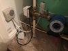
The system is a Potterton Promax SL condenser boiler, pumped rather than gravity fed with a hot water cylinder in the airing cupboard. It has a three port valve which I believe means its a 'Y Plan' configuration.

I have attached photos of;
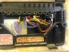
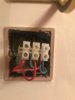
- the wiring on the EP3002 (wires painted with white does to aid identification),
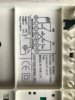
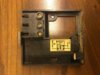
- the wiring diagram on the EP3002
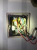
- the wiring in the airing cupboard
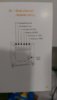
- the HIVE receiver wiring diagram
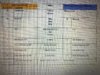
- the document I prepared to map the wires from the EP3002 to the Hive receiver.

I have approached an heating engineer for help and am awaiting their response. Any help/advice in the meantime would be very much appreciated.
 

Attachments

  • Hive Dual Channel Wiring Diagram.jpg
    Hive Dual Channel Wiring Diagram.jpg
    109.8 KB · Views: 858
  • EP3002 Wiring Diagram.jpg
    EP3002 Wiring Diagram.jpg
    93.5 KB · Views: 735
  • EP3002 Wiring configuration.jpg
    EP3002 Wiring configuration.jpg
    111.5 KB · Views: 679
  • Mapping document.jpg
    Mapping document.jpg
    294.8 KB · Views: 499
  • Airing Cupboard Wiring.jpg
    Airing Cupboard Wiring.jpg
    80.7 KB · Views: 457
Sponsored Links
The Hive should replace the EP, you can't have two programmers wired in circuit at the same time. Unless you understand where every wire goes and what it does, the easiest way to DIY install is to simply swap the EP for the Hive as the wiring is almost identical. So personally, I would be inclined to put it back as it was before and then once you've made sure that it's working, start again.

Whilst it can look complicated. The EP contains standard programmer connections, plus some additional terminals that don't have any other purpose than to connect the wires that are in them together. The Hive doesn't have this facility, so new connectors will have to be provided to contain these wires. The tricky bit is finding space for them. I generally sink a back box in the wall behind the Hive receiver to enclose the new terminals and just bring the wires needed for the Hive through to the Hive backplate. Having said that as only 'D' is used on your case it shouldn't be too much of a problem.

A note of caution though. Make sure you identify and mark each of the wires. If you unwittingly transpose a two of them it can be extremely difficult to fault find, without tracing each wire individually and knowing what is connected to the other end of it.

So starting with the programmer part, electrically speaking you are just changing one switch for another identical switch. The EP has the connections as below.

ep-jpg.157374


The wires from the EP move to the Hive connections that have the same function, and in your case the EP terminals N, L, 1, 2, 3, 4 correspond exactly with the Hive. The wire link presently in the EP between terminals L and 5 is discarded as this is already made for you inside the Hive, so the Hive doesn't need, or have a terminal 5. Unfortunately I can't see clearly in your photo where all of the wires go, but any other wires in 5 apart from the link need to remain connected to 'L'


hive-jpg.157375


The EP right hand vertical terminal strip is for the earth wires, there aren't any in there, but wherever they are they should remain connected together. An earth connection should also be made to any new back box if it is metal.

The EP left hand vertical terminal strip is for the neutrals, I can't see it in the photo, but it doesn't appear to be used. If it is, the wires should remain connected as they are.

Terminals A, B, C & D are not connected to the workings of the EP, they are simply connectors that are provided for the installers convenience. So the wires in 'D' need to remain connected together.

Finally any existing room thermostat should be decommissioned, by linking the live switching wires together so that it doesn't interfere with the operation of the Hive, it can't just be disconnected otherwise the heating wiring would remain 'open circuit' and the heating will not operate. If you need any help with this then post back details of the existing room thermostat.
 
Last edited:
Hi Stem,

Many thanks for taking the trouble to respond. I have triple checked the wiring and am sure I haven't transposed anything when wiring up the Hive receiver. There were two wires connected to connector D (Yellow & Brown) and I have moved those to a terminal block. There was also a wire between L and connector 5 which I have removed. I have attached some photos of the thermostat which I hope will help;
- Front Cover
- Backplate
- 2 picture of the wiring.

There are two cables coming in but one may connect to the Frost stat which is adjacent? You will see that I have removed the thermostat and put the wires into terminal blocks - they correspond left to right to the connectors on the stat backplate (H = Red L=Red N= 2 x Blue). The two yellow wires are also in a terminal block but that was already like that when I removed the cover.

Hope this helps.
 

Attachments

  • Thermostat wiring 1.jpg
    Thermostat wiring 1.jpg
    53.5 KB · Views: 352
  • Thermostat wiring 2.jpg
    Thermostat wiring 2.jpg
    114.1 KB · Views: 350
  • Thermostat backplate.JPG
    Thermostat backplate.JPG
    349 KB · Views: 338
  • Thermostat cover.JPG
    Thermostat cover.JPG
    188.7 KB · Views: 315
If it's been installed properly the frost stat wiring shouldn't change, because the frost stat should override the normal controls to turn the heating on when there's a risk of freezing even if the heating is set to be off. Unfortunately without knowing what is on the other end of each of the wires going to it, I can't really say more than that.

The existing room thermostat can be decommissioned by tracing the cable from the PRT room thermostat back to its origin.
Note where the wires that go to the thermostat 'L' and 'Heating' terminals are connected.
Disconnect the old thermostat cable completely and remove it
Add a wire link to join together the terminals where the wires from the thermostat the thermostat 'L' and 'Heating' terminals terminals have just been removed from.

Alternatively, a less professional method, but one that's easier, is to leave the old room thermostat in place, remove the wires from the thermostat 'L' and 'Heating' terminals and join them together inside it using a separate isolated connector.
 
Sponsored Links

DIYnot Local

Staff member

If you need to find a tradesperson to get your job done, please try our local search below, or if you are doing it yourself you can find suppliers local to you.

Select the supplier or trade you require, enter your location to begin your search.


Are you a trade or supplier? You can create your listing free at DIYnot Local

 
Back
Top