- Joined
- 4 Jan 2024
- Messages
- 7
- Reaction score
- 0
- Country

Hello there, long time lurker first time poster. But I've found these forums really useful as we embark on our extension project.
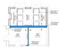
We're taking out a 5.3m span of external wall (brick and block), bearing the first storey above and roof, and 2.7m internal wall carrying the joists (which run across the house) to make for an open plan with a new rear extension, as you can see in the pic below. I was just looking for some reassurance or pointers in relation to the SE's design and calcs for the UBs. I'm going to phone them for my peace of mind but wondered what sorts of questions you might be asking in a situation like this?
My thoughts were:
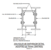
- I understand the standard bearing on a padstone is 150mm so why would they have gone for 140mm (even if the calcs say this is okay)?
- I've seen sometimes people say that an SE has said foundations require reinforcement, but often on this forum people post that's unnecessary. There is about 1.2m brickwork below ground, on top of a raft foundation (not sure how deep as with BC agreement the builder stopped digging the new founds at 1.4m). Given the point load spreads out is it reasonable to assume that by the time it reaches the foundation this will be spread?
- The SE hasn't specified rebuilding the remaining walls in engineering brick. It's a 1970s house, facing brick some sort of Tudor London with internal block. Is it reasonable to assume that it can take the compression?
Is there anything else that I should be concerned/questioning about? We have a competent builder who has seen and done it all before and tells me to trust the process, but understands I'd like peace of mind.

We're taking out a 5.3m span of external wall (brick and block), bearing the first storey above and roof, and 2.7m internal wall carrying the joists (which run across the house) to make for an open plan with a new rear extension, as you can see in the pic below. I was just looking for some reassurance or pointers in relation to the SE's design and calcs for the UBs. I'm going to phone them for my peace of mind but wondered what sorts of questions you might be asking in a situation like this?
My thoughts were:
- I understand the standard bearing on a padstone is 150mm so why would they have gone for 140mm (even if the calcs say this is okay)?
- I've seen sometimes people say that an SE has said foundations require reinforcement, but often on this forum people post that's unnecessary. There is about 1.2m brickwork below ground, on top of a raft foundation (not sure how deep as with BC agreement the builder stopped digging the new founds at 1.4m). Given the point load spreads out is it reasonable to assume that by the time it reaches the foundation this will be spread?
- The SE hasn't specified rebuilding the remaining walls in engineering brick. It's a 1970s house, facing brick some sort of Tudor London with internal block. Is it reasonable to assume that it can take the compression?
Is there anything else that I should be concerned/questioning about? We have a competent builder who has seen and done it all before and tells me to trust the process, but understands I'd like peace of mind.