RSJ to support rafters

Joined
11 Apr 2006
Messages
2,154
Reaction score
201
Location
Berkshire
Country
United Kingdom
I think I have a problem with my plans the RSJ I'm using to support my rafters. Although my SE has proved it will take the loadings, the designer (me) didn't fully think through the installation in terms of rotational support.

The thought process was as follows:

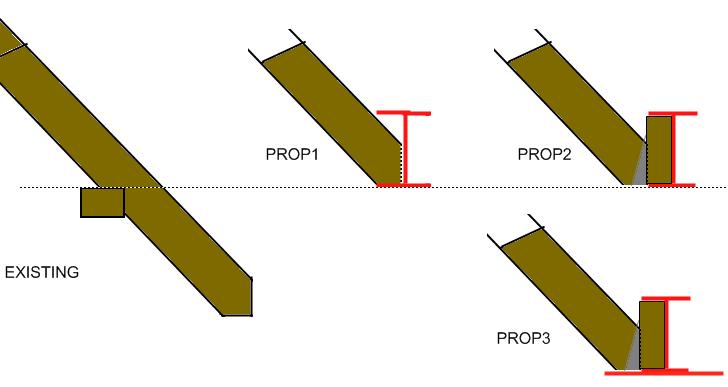
In 'existing' on the diagram below, the rafter sits on the wall plate.

Proposed1 shows the initial concept where the rafters are trimmed at wall plate level then the existing birdsmouth is sat on the bottom flange of the RSJ.

Proposed2 is a progression on this concept to bolt a captive wooden joist into the RSJ so that hangers can be used, rather than having to fix noggins between every rafter.

This is where the problem lies. Because this joist is up at wall plate level there will be very little masonry to stop any downward force from the rafter feet rotating the joist counter-clockwise as you look at it.

So perhaps I should have asked the steel firm to have welded a couple of large feet to the joist as per Proposed3. But it's too late now.

So I want to return to Proposed1. Can I fix noggins between the rafters using framing anchors, or will each 400mm noggin need to be bolted in place?

Thanks as always!

 
Sponsored Links
Others, with far more experience than me, might come along and perhaps have more definitive things to say about your proposal - but what exactly did the SE calculate?

What is your project?

Can you scan full section and plan views?

How can "proposal 3" be viable if it's "not possible now"?

Is the steel on site? In situ? Have any rafters been cut?
 
Gary, my boy, of the top of me head, would say you could be in deep sh*t with your proposals, and not just for the reasons mentioned.
Will give it some thought tomorrow and post you some questions to refresh our memory of existing roof and ceiling where you are going to fly in.
Regards oldun.
 
Hi Tim00 - Proposal 3 has a much larger flange welded to the RSJ therefore preventing any rotation. No rafters cut yet. Steel is on site, not in situ.

The purpose of the RSJ is to support the rafters/wallplate where a wall is to be removed on the first floor to knock through to an extension. The SE has calculated the loadings and specified the RSJ and padstone required.

I could fit the RSJ directly below the existing wall plate, but I don't have the ceiling height for that.

Oldun - Thanks! The RSJ is directly beneath the 'fly-in' where the new extension meets the house.

Gary
 
Sponsored Links
The RSJ is in the heart of this cross section, currently labelled 'doubled up joists'


This plan view shows the existing house rafters, and new extension at joist level with lay boards to support fly-in.


Plan at rafter level

 
If that beam is the red bit in the second image, then it seems like the beam is not doing much because those existing rafters are redundant.

The new roof junction can be loaded to the existing hip, and if need be, a new hip put in on the other side and the existing ceiling joists extended over the beam and supported vertically off it
 
Hi Woody,

Yes, that's true. Unfortunately the SE couldn't prove the existing hip so then that would need replacing too, and then that would lead to the same issue with the existing main roof ridge plate, king post, etc. I was advised against it, and BC seem happy with the approach. Generally, the whole existing roof is ~1950's so most members fail modern tests (Apparently)

Therefore the extension fly-in is on lay-boards resting on the rafters, which in turn are supported by a) a purlin at half span, b) the wall plate.

Gary
 
I am open to correction, but I always thought that there was minimal loading on hip rafters in normal situations - which is why they have never been in any span tables.

I can't see why there is a need for that beam. Nor can I see why the engineer did not design a working solution.

However, the engineer should have designed a beam to take any loads, so if that is his design then it should work, shouldn't it?
 
The RSJ is only 79mm x 127mm x 13, so it's a tidler, and that probably reflects the small loadings involved.

The SE specified the beam to take the load and told me that it doesn't matter if the after tails sit on the top flange or bottom flange, but I'm getting hung up on the detail of how to actually do this. My intuition tells me it's not stable.

I'll go back to the SE for clarification.
 
I am open to correction, but I always thought that there was minimal loading on hip rafters in normal situations - which is why they have never been in any span tables.

woody, no way do we wish to try to correct you, as in all our years we have heard so many arguments about valley and hip rafters, the role that Kings, Queen and Jacks play that we have come to the conclusion that we have not yet met anyone who really knows.
We stick to the rule of thumb that we were taught many years ago. 2.5 times depth of existing rafters and 1.5 times width of existing rafter with additional bracing under wrap round purlins.
Have never had lid collapse on us yet, so must be in right field.
Regards oldun.
 
Gary, Questions, and every one has a purpose..
1. Is first floor proposed level and existing first floor level the same, or is there a step.
2. Height of top of existing wall plate above floor level
3. Ditto new extension.
4. Confirm existing house has a raised tie ceiling.
6. If so height of existing ceiling joists above plate and method of securing joists to rafters.
7. Size of existing rafters and ceiling joists
8. Will joists of new extension sit on plate or be raised tie.
9. From memory existing house was 50mm cavity and new extension 85mm thereby changing HAP where roofs join. Is this correct
10.Note that internal width of new extension is 4044 and would appear that knock through is same width. If so what end bearings have you allowed for on USB and what size is USB.

Quick observations. Until we receive your answers, would appear that USB will be above HAP of rafters at both ends and will need to be chamfered down and a new 7.8mm flange welded to web. We are not SE, but we note that you say your SE has proved the beam loading, but we ask the question has he proved the loading, rotation and deflection in the way that you intend to use it???
Looking at the existing house from back garden, you can use a lay board on the right hand side where valley gutter runs up, but not on the left hand side where roofs join into one and other. on the (hopefully) same plane.. You will not get a straight run from ridge to HAP with a layboard underneath jacks. Think about it, draw a small sketch and you will see what we mean. Two ways of getting round this situation.. 1. Treat existing hip rafter as valley rafter and run valley jacks up to ridge in as near a straight line as possible to existing hip jacks. At times we have laminated in between existing hip jacks 100mm onto hip rafter to make this possible. 2. If existing rafters deep enough, drop layboard down onto noggins between existing hip jacks and then fly jacks from this to ridge. .
To know your dead loads what tiles are on existing roof.>
Regards oldun..

Note your beam size on your last post.
 
Just another thought.

If the beam is adequate for the loads, then I'd go with prop 2, but with another timber bolted through the web on the back (like a flitched beam), and then with some timber braces across the top of the beam at 90° - and fixed to the existing rafters (every third rafter)and across a few of the new ceiling joists

This should deal with any possible rotation
 
Hi Oldun - thanks for the long reply!

1. Yes, new floor level matches existing floor level.
2. Top of existing wall plate is 2590 above floor level.
3. Top of proposed wall plate is 2550 (40mm difference allow for extra depth from 195mm rafters after birdsmouthing etc)
4. Yes, existing ceiling joists are raised tie.
6. Top of existing wall plate is 154mm below existing joists/ties. Ties are nailed into rafters by two nails.
7. Existing rafters are 100mm x 50mm @400c. Existing joists 100mm x 50mm @ 400c
8. New extension joists will sit on wall plate.
9. Yes, this is correct. CONFIRMED - This is a 20mm difference. I need to revise my 40mm planned difference in wall plate heights in point 3 above as previously I expected this difference to be 35mm.
10. End bearing on the perpendicular wall is 100mm. On the corner wall it is 150mm.

Until we receive your answers, would appear that USB will be above HAP of rafters at both ends

Yes - that's what I conclude from the drawings too.


and will need to be chamfered down

My calculations show that I might just get away without chamfering the corners to clear the roof line, but I think there's only 5mm in it so difficult to be sure.

and a new 7.8mm flange welded to web

I'm not sure I follow here - is that in order to provide a wide enough platform for the rafter feet?


We are not SE, but we note that you say your SE has proved the beam loading, but we ask the question has he proved the loading, rotation and deflection in the way that you intend to use it???

Perhaps not - I have tried to contact him this afternoon.

Layboards

I need to have a careful read through what you've written and have a think about it / understand it.

To know your dead loads what tiles are on existing roof.

They are concrete tiles normally called rosemary/acme - approx 200mm x 300mm - I will confirm.

Thanks

Gary
 
Hi Woody,

Excellent - yhat seems to make sense - I'll take a look at the levels tonight and see what's practical in that train of thought.

Cheers

Gary
 
Quote:and a new 7.8mm flange welded to web

I'm not sure I follow here - is that in order to provide a wide enough platform for the rafter feet?

What we mean, is that when we angle cut down a steel at the ends to drop top flange below rafter line, we take an addition 15mm of in depth on the web and then weld a new say 10mm flange on the top of angled web from top flange to bottom flange to put some meat back into steel at the ends.

1. Sorry for delay.
2. According to your figures, storey heights are high, even for 50s build.
3. With that in mind would be tempted to fit your sardine can (steel) underneath the plate.
4. Reasons. Stronger and easier. Will save cutting beam. Solves problem of possible rotation and deflection Will still leave you with 2380 headroom which is approx modern day storey height..
5. If you do not like thought of dropped beam at this point then disguise it with either semi circle or elliptical pre formed arch turners at each end with bridging piece and make a feature of the beam.
6. If you still wish to stick beam up into void, then go along with the suggestion of woody. Proposal 2, but strut against any possible rotation in the ceiling joists of new extension
7. GIVE BIT MORE THOUGHT TO PROPOSED POSITION OF LOFT HATCH. MAKE SURE YOU CAN GET THROUGH IT.
Regards oldun
 

DIYnot Local

Staff member

If you need to find a tradesperson to get your job done, please try our local search below, or if you are doing it yourself you can find suppliers local to you.

Select the supplier or trade you require, enter your location to begin your search.


Are you a trade or supplier? You can create your listing free at DIYnot Local

 
Sponsored Links
Back
Top