RSJ vs concrete lintel - 8foot span

Joined
6 Nov 2015
Messages
25
Reaction score
0
Country
United Kingdom
Good morning all...

I would like to remove the wall between the kitchen and the dining room. The house is a semi detached chalet bungalow. it appears that many of the neighbours have done this in differing ways, but my plan is to have a pillar either side of the opening where the support will sit on, creating a kind of arch. There will be a drop of a block and then whatever supporting lintel I use (RSJ or concrete etc.)

The span will be around 8foot (2.4m). I had originally thought I would need an RSJ (152 x 89 x 16kg ). a builder came out last night to see the job (as I am running out of time to DIY it) but he is busy and said he could lend a hand but doing the job would be difficult to fit in. he suggested that a concrete lintel might do the job and it seems very easy.

the house is a standard 3 wall support (interior block walls), outside walls, and a centre wall supporting the roof and upstairs bedrooms.

The wall i want removed, runs perpendicular to the supporting walls (outside back wall to the centre wall). however, there is a steel I-beam running in the roof space running half way across the house and a wooden beam running the rest of the house. they of course meet in the middle, right on this wall I want to remove. (they support the roof)

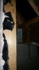
below you can see pictures of the top of the wall, inside the roof space. you can see there are a few lines of blocks built up to support the wood and steel beams. the first picture shows the start of the wooden beam, and the end of the steel beam (not sure why they mixed it up, but suspect cost when house was built)

I do not know much about concrete beams, are they suitable for a job like this? might one give a better finish than the I-beam (i.e. easier to finish off with plaster and what not)?

plan would be 2 sets of acro's, one above the door frame and one below the i-beam itself...

appreciate any help or advice... once I have the plan, I can order stuff and get BC in to review

20151030_134203_resized_1.jpg
20151030_134213_resized_1.jpg
house view after.JPG
house view before.JPG


due to the static-load above it.
 

Attachments

  • 20151030_134159_resized_1.jpg
    20151030_134159_resized_1.jpg
    55.2 KB · Views: 304
Sponsored Links
as you can see from the pictures, the load above this opening would be static (apart from the very left of it where the landing is), the majority of the opening will be underneath the roof space, and only the centre part is actually load bearing under the i-beam/wooden joist.
 
There is quite a bit of load getting to the existing wall (and therefore any beam / lintel installed). The loads need to be calculated and a section designed. It's not as simple as just getting an off the shelf concrete lintel as their load tables are usually in kN/m run or kN total load. Your loadings aren't uniform so in order to use a concrete lintel you would need to calculate an equivalent UDL (kN/m) or equivalent total load (kN) from the bending moment induced by the existing loadings. The purlins will be taking a lot of roof load to a point above your beam.

Find someone who knows what they are doing to calculate a section for you.

As for plastering, it's not that difficult to finish a steel beam as you can simply bolt some timbers either side of the web and underneath if necessary and nail or screw on some plasterboard.

Also, don't forget that if you haven't got any lifting gear a small steel beam will be much lighter and easier to lift into place.
 
Last edited:
thank you so much for the reply. I think the way to go is steel, as it takes more risk out of it and like you said finishing it is not that bigger deal. the problem is, I had it all right in my head until the builder came around and muddied my brain a little. his intentions were great of course as he came at short notice but just does not have time to do the job himself.. (would much prefer this :) )
 
Sponsored Links
in that side-long picture of the house I drew above, I have the i-beam going the length of the house, but in fact it terminates on this wall, and a wooden beam is used for the other half of the house...
 
in that side-long picture of the house I drew above, I have the i-beam going the length of the house, but in fact it terminates on this wall, and a wooden beam is used for the other half of the house...
Yeah, got that. So half the load from the timber purlin, and half the load from the steel purlin ends up on your lintel. Plus some floor load and storage load presumably. Needs to be calculated.
 
out of interest, how does the engineer calculate it? i.e. without the original design of the house? it must be a bit of a dark art, as the roof is supported by the main roof structure itself, which is supported by the outside and inside walls. this set of beams then also support it along the length.. it can not be easy to work out the strength of a beam needed in such a situation...
 
out of interest, how does the engineer calculate it? i.e. without the original design of the house? it must be a bit of a dark art, as the roof is supported by the main roof structure itself, which is supported by the outside and inside walls. this set of beams then also support it along the length.. it can not be easy to work out the strength of a beam needed in such a situation...
The engineer will either work from drawings or visit the property to ascertain the structure and calculate the loadings based on what is observed. In this situation the purlins will be assumed to support the roof load between them and the next supports in each direction - i.e. the external wall of the house and the purlins on the opposite side (this is assuming that there is no ridge beam). The first floor level walls are non load bearing so only the self weight of those walls will be taken.
The direction of the floor joists will be determined and depending on their span load may or may not be taken to the wall. Any additional loads on the joists / trimmers will be allowed for, such as the self weight of the first floor walls. The self weight of the blockwork will also be determined and added to the beam as a partial UDL.
There is an allowance for domestic imposed loadings from the first floor, and there should also be an allowance for storage in the dormers. All of the above loadings can be estimated using the relevant British Standards.

Once all of the above has been done the forces, moments, and deflections can be calculated and a section size determined.
 
that's great, thank you so much for that description. every day is a learning day they say!
 
out of interest, how does the engineer calculate it? i.e. without the original design of the house? it must be a bit of a dark art, as the roof is supported by the main roof structure itself, which is supported by the outside and inside walls. this set of beams then also support it along the length.. it can not be easy to work out the strength of a beam needed in such a situation...
The engineer will either work from drawings or visit the property to ascertain the structure and calculate the loadings based on what is observed. In this situation the purlins will be assumed to support the roof load between them and the next supports in each direction - i.e. the external wall of the house and the purlins on the opposite side (this is assuming that there is no ridge beam). The first floor level walls are non load bearing so only the self weight of those walls will be taken.
The direction of the floor joists will be determined and depending on their span load may or may not be taken to the wall. Any additional loads on the joists / trimmers will be allowed for, such as the self weight of the first floor walls. The self weight of the blockwork will also be determined and added to the beam as a partial UDL.
There is an allowance for domestic imposed loadings from the first floor, and there should also be an allowance for storage in the dormers. All of the above loadings can be estimated using the relevant British Standards.

Once all of the above has been done the forces, moments, and deflections can be calculated and a section size determined.


....................or just fit a 152 x 89..............:D
 
Seriously, I think a 152x89 would do across that span. I wouldn't even put a pier against the outside wall (though the internal end would need a nib).

What I wouldn't do is fit a concrete lintel. Many of them are 'composite' and gain strength by the bonding with new masonry above, and are not suitable for breakthroughs in existing walls.
 
I think Tony is probably right that a 152x89 is OK for that span - if the top flange has some restraint to it.

However, this is a situation where your friendly BCO may well want to see calcs so you may still have to get some calcs done to satisfy building control.
 

DIYnot Local

Staff member

If you need to find a tradesperson to get your job done, please try our local search below, or if you are doing it yourself you can find suppliers local to you.

Select the supplier or trade you require, enter your location to begin your search.


Are you a trade or supplier? You can create your listing free at DIYnot Local

 
Sponsored Links
Back
Top