- Joined
- 24 Nov 2004
- Messages
- 463
- Reaction score
- 7
- Country

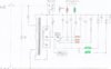
is this (attached schematic) "phase converter" drawing correct?
I have attempted to draw out the circuit of a machine that I have.
I think it is a static phase converter, which as far as I can make out is essentially a start/run capacitor system for getting a 3-ph motor turning, at which point the motor falls back to being supplied by 2 phases
it does of course have a large transformer, wired as an autotransformer (I think) but that appears only to be increasing the voltage.
the machine has this "boost" function controlled by the voltage sensitive relay, which seems to be the start capacitor(s)
why is it called "boost"? I could understand if the boost function was increasing voltage but I can't see that happening in this arrangement