Let's get back to OP.
Chances are this is a 2 phase motor,
Chances are the N terminal is a functional N terminal,
Chances are P1 requires one of the phases to be connected to it,
Chances are P2 requires a different phase to be connected to it.
IF the above is correct and I emphasise IF, the second phase is derived from the same 230V supply as P1 by adding a series capacitor to provide a phase shift.
IF all of the above is correct, reversing the connexions to P1 & P2 the motor will run in the oposite direction.
Most of the reversible motors I have got involved with (a very small sample) they have worked on some sort of version off this description.
As there are so many variations on the way single phase motors are built it is quite easy for this post to be totally irrelevant in the case of the OP's motor.
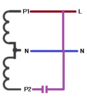